
- Joined
- May 27, 2010
- Messages
- 2,364
- Motherboard
- Dell Optiplex 9030 All in One
- CPU
- i5-4690K
- Graphics
- HD 4600
- Mac
- Classic Mac
- Mobile Phone
Hi all,
I've seen a few people ask for this over the years, but had not seen it posted. I was just going to bypass the switch etc. on my mod but looking at it it all looked pretty easy to work out with a multimeter.
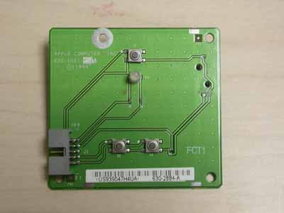
Here is the pic of the circuit itself:
stock_board-4983_0.jpg
Top tact switch (S1) of course is the power switch, bottom left (S2) is the reset switch, bottom right is the "programming switch" (S3).
Here is the pinout (so I have got it written down and to help others!).
If you cut the ribbon cable coming from the board and want to wire PC connectors to it, do the following.
cables.jpg
Lay the cable flat with the single red cable on the left. Cables from left to right (or top to bottom on my photo) and with numbering 1 to 10 and with the PC functions marked by me in green are:
1.S3+ programming switch; Don't use.
2. No connection.
3.S2+ Reset switch.Use for reset switch + if you want
4. No connection.
5. S1 +; Use for Power Switch +
6. No connection.
7. Not useful (part of the apple circuit).
8. COMMON GROUND; Use for Power Switch -
9. Anode 1 (glows LED Green); Use for Power LED +
10. Anode 2 (glows yellow); Don't use.
This numbering is also the same as Apple use on the circuit board.
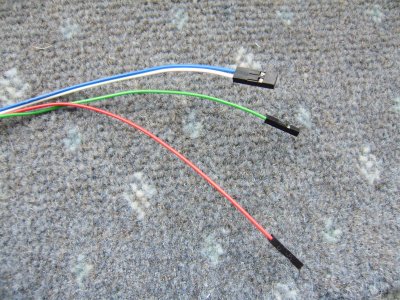
P3110469.JPG
This photo above just shows the connections you will be left with. The blue and white is the power switch connection (Blue = +ve and connects to cable 5 of the ribbon; White = common ground and connect to cable 8 of the ribbon); the green wire (connected to cable 9 of the ribbon) is to go to the + connection on the motherboard for the Power LED to glow green when the PC is on.
The red wire in the picture I connected to cable 10 on the ribbon, just for experimenting but I am NOT using on my board as I don't like the yellow and it does not flicker with HDD activity and just glows sickly yellow. I did not bother with hooking up the reset switch yet as I have no use for it. It does work though and has been tested.
Please note that this board uses a common ground and that is fine - all the functions on an ATX for LEDs and Switchs also have a common earth so as long as wire 8 is actually connected to a ground (best and easiest to use it to connect to the power switch ground) the board will work fine for us without needing to get down and dirty with the circuits. What I mean by this is that the LED and reset switch etc. only need to have their positive side connected at the PC motherboard. There is absolutely no need for cutting of PCB traces for this module to work - it's all fine and good to go with just the simple wiring job detailed above.
Hope this is useful to all and another good resource for G4s!
I've seen a few people ask for this over the years, but had not seen it posted. I was just going to bypass the switch etc. on my mod but looking at it it all looked pretty easy to work out with a multimeter.
Here is the pic of the circuit itself:
stock_board-4983_0.jpg
Top tact switch (S1) of course is the power switch, bottom left (S2) is the reset switch, bottom right is the "programming switch" (S3).
Here is the pinout (so I have got it written down and to help others!).
If you cut the ribbon cable coming from the board and want to wire PC connectors to it, do the following.
cables.jpg
Lay the cable flat with the single red cable on the left. Cables from left to right (or top to bottom on my photo) and with numbering 1 to 10 and with the PC functions marked by me in green are:
1.S3+ programming switch; Don't use.
2. No connection.
3.S2+ Reset switch.Use for reset switch + if you want
4. No connection.
5. S1 +; Use for Power Switch +
6. No connection.
7. Not useful (part of the apple circuit).
8. COMMON GROUND; Use for Power Switch -
9. Anode 1 (glows LED Green); Use for Power LED +
10. Anode 2 (glows yellow); Don't use.
This numbering is also the same as Apple use on the circuit board.
P3110469.JPG
This photo above just shows the connections you will be left with. The blue and white is the power switch connection (Blue = +ve and connects to cable 5 of the ribbon; White = common ground and connect to cable 8 of the ribbon); the green wire (connected to cable 9 of the ribbon) is to go to the + connection on the motherboard for the Power LED to glow green when the PC is on.
The red wire in the picture I connected to cable 10 on the ribbon, just for experimenting but I am NOT using on my board as I don't like the yellow and it does not flicker with HDD activity and just glows sickly yellow. I did not bother with hooking up the reset switch yet as I have no use for it. It does work though and has been tested.
Please note that this board uses a common ground and that is fine - all the functions on an ATX for LEDs and Switchs also have a common earth so as long as wire 8 is actually connected to a ground (best and easiest to use it to connect to the power switch ground) the board will work fine for us without needing to get down and dirty with the circuits. What I mean by this is that the LED and reset switch etc. only need to have their positive side connected at the PC motherboard. There is absolutely no need for cutting of PCB traces for this module to work - it's all fine and good to go with just the simple wiring job detailed above.
Hope this is useful to all and another good resource for G4s!

 Aboout time someone took the time to figure this out
 ") It is super appreciated. Looks like I have my weekend project
It is super appreciated. Looks like I have my weekend project