Contribute
Register

NUC in a Mac Mini case

Status
Not open for further replies.
Minihack, are you still considering the separate GPU? I was on a hunt for a half-mini to PCIe adapter to hook up a capture card and ran across a nice selection of stuff from Amfeltec. They have a variety of host boards (PCIe/mini PCIe/Half Mini PCIe) and a selection of slot boards (1x, 4x, 16x) with a variety of power options from powered by the host card, 12v power or ATX power. I contacted them and they can mix and match them however you like.

For example, the unlisted SKU-035-19 part number is a MiniPCI Express (half) to x16 PCI Express Adapter, ATX powered. I'm sure they have a SKU for a half-mini to x16 12v powered combo.

Kinda pricy... that combo is $72.

http://amfeltec.com/products/flexible-minipci-express-to-pci-express-adapter/

They also have Mini PCIe splitters that look interesting.

Edit: Ahh... it was DJ that suggested the GPU card... ahh well, maybe their splitter might be an option to move the flash drive, for better cooling, and still keep another slot available for something else.
 
...
The worry for me though is the mSATA. I ran Black Magic Speed Test (looping in the background) and did some geek bench testing and after not too long the temp of the mSATA went up to 72C (according to HW Monitor). At that point CPU temp seemed to have topped out in the high 40s.

The mSATA though, even when doing nothing much at all seems to creep up into the mid 50s.

I did a little googling and it seems the M500 series mSATAs do tend to run hot, but I think for some peace of mind I will need to cool it down. Unfortunately this probably does mean hooking up and internal fan as I don't think there is any way I can get the surface of the mSATA to contact the case material….
have you considered mounting small passive heatsinks to the flash chips, to at least allow the heat to disapte out of the chips. I would try this first, height allowing.
 
Cheers Kiwi,
Yes I've got some of those in a drawer somewhere. There are chips on both sides of the SSD though but at least it should help the ones on the top surface.
 
The mSATA though, even when doing nothing much at all seems to creep up into the mid 50s.

I did a little googling and it seems the M500 series mSATAs do tend to run hot, but I think for some peace of mind I will need to cool it down. Unfortunately this probably does mean hooking up and internal fan as I don't think there is any way I can get the surface of the mSATA to contact the case material….

maybe you can take some ideas from this design;

http://www.impactics.com/d3nu1-b/olympus-digital-camera-63/
 

Attachments

  • image.jpg
    image.jpg
    111.1 KB · Views: 293

That's interesting - not sure if I have room for that yet. I'll have to look into it if the idea of a simple RAM heatsink isn't enough.

I am wiring up the touch switch today……interested to see if that works out when wired in properly and whether it gets affected by heat issues (I've heard capacitive switches can be a bit sensitive).
 
Okay, so far so good.

I am now doing a longer test and have hooked the NUC up to wifi (recycling a pair of Mac Pro Antennae - sig seems fine). I put some heatsinks on the mSATA after removing the sticker.
IMG_1223.jpg

With the case buttoned up and just web browsing, and writing this, temps for the CPU are pretty much stable around 35C, my Toshiba laptop drive is 26C and the mSATA is sitting at 49C - which is certainly an improvement over where it has been, but I have a feeling it is likely to rise more as I continue [will report back].

In the meantime, here are a few more pic.s:

This is the external "pad" I made for the touch sensor following the suggestions for the breakout board:

IMG_1216.jpg


Once I installed the roof tray for the NUC, this is all you can see of it from the inside:

IMG_1224.jpg

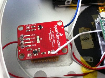
And here is the actual touch sensor board in current location:

IMG_1222.jpg

The PCB is attached to a vero board via a header and on the vero board I have attached my 5v DIL reed relay circuit. Connections are 5Vsb goes to Vdd, Out goes to one end of the energising coil of the relay circuit (other end to GND), the switch terminals for the NUC go to the switched outputs of the relay circuit. Only other connections are the pad sensor and my LED indicator (which is attached to the OUT terminal of the touch switch PCB via a 220 ohm resistor).

EDIT: After an hour or so of gentle use it seems mSATA temp has stabilised at 52/53C. Warmer than I would like, but a long way short of the upper limit Crucial set for this model of 70C when it starts to throttle back performance.
 
Short vid of Touch sensor operation.

[video=youtube_share;nNUuxtCTpds]http://youtu.be/nNUuxtCTpds[/video]
 
Latest news is that the sensor board, having proved to be reliable, is now properly installed in the case. Incidentally I think this could be another great option as a substitute for a Cube touch sensor switch as the data sheet claims it can be made to work through 10mm of acrylic.

gpkr8.jpg


qqd5.jpg


The board is mounted by screws to a small acrylic square that is epoxied into the case and small nylon cap nuts hold the assembly down.

You can also see from these pic.s that I installed a new incredibly slimline SATA data cable that has really flexible wires and must be just about the lowest profile on the market. The bad news is each cable costs £7!! Here is where I got it from: http://www.overclockers.co.uk/showproduct.php?prodid=CB-039-SV

Another thing to note here is the pair of Mac Pro Antennae for the wifi/BT which are an ideal length and flexibility to allow mounting on the plastic base and keeping it instantly removable.

Also note the two holes I made in the Mini case so I can use an Allen key to undo the harder to get to bolts that hold the NUC in place on the roof tray. This seemed the best compromise as I do not want anything to be non-serviceable.

Next up will be adding the extra rear ports from the Bitfenix Shinobi board. It arrived today, and needs some surgery to fit. I will be trimming both ends of the PCB and cutting off one USB 2 port to make it fit and then I will be shortening all the cables and also splicing in the audio cables to a combined mic/headphone jack.

After that I may then play with cooling of the mSATA chip again (temp.s remain around 55C for it) as I have some 0.9mm copper sheet coming that I will investigate bending and using as a clamping mechanism to draw heat off from the chips and down to the Mac Mini case.

Once that is done I can set about making a rear panel to finish off the project…..:)
 
Nice work! It would be tempting to use the OEM PSU with the space available! Its rated at 12v, 7.1 amp. Does the NUC require more than 12v?
 
Status
Not open for further replies.
Back
Top