Contribute
Register

neilhart's Mac Pro Hack

Status
Not open for further replies.
Fans and Cooling:

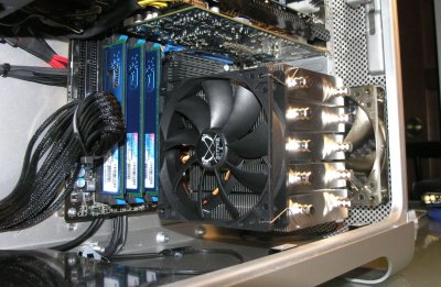
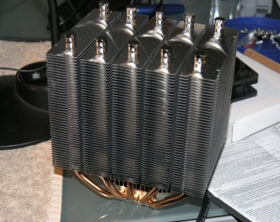
The Intel i7-950 rating Max TDP of 130 watts influenced my choice of CPU cooler. Bigger is better (probably not) but I choose the Scythe Mugen ? 2B which is huge. The cooler comes with on Scythe “Slip Stream” high airflow 120 mm fan which I used on the cooler.
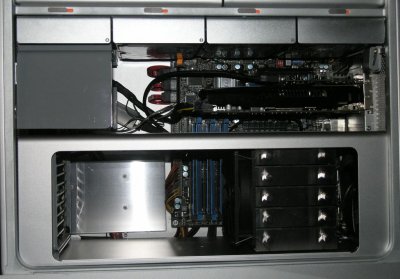
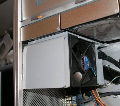
I chose two SiLenx 120 mm fans, one for the front and one for the rear. I purchased a late model Mac Pro Processor Cage from an Ebay seller and cut it a part to use the top, front and bottom portions. I installed the front SiLenx fan into this cage and added a 1/16 acrylic window. The rear SiLenx fan is attached directly to the Apple rear fan grill.

This forms a three fan tunnel for cooling the CPU.

I cut down the original dual front fan plastic tower and reconfigured it to house a 92mm Scythe Kama-Flex fan.

These fans are all powered by the MSI motherboard which has BIOS level speed control capability. I am not sure yet how much speed control actually is present running in OS X Lion. But the point of these selections was to keep the noise down.
Total fan count is 6 (way too many and will surely require service at some point).
 

Attachments

  • Fan-tunnel-1.jpg
    Fan-tunnel-1.jpg
    122.1 KB · Views: 2,854
  • Fan-tunnel.jpg
    Fan-tunnel.jpg
    137.1 KB · Views: 2,697
  • upper-fan-mod-brkt.jpg
    upper-fan-mod-brkt.jpg
    135.4 KB · Views: 2,604
  • CUPcooler-w-fan-installed.jpg
    CUPcooler-w-fan-installed.jpg
    160.5 KB · Views: 2,528
  • Mugen.jpg
    Mugen.jpg
    184.1 KB · Views: 2,201
neilhart said:
Front panel and wiring (includes the USB/Firewire board).

Okay the credit here goes those that have gone before and documented the task.
The most recent documentation is/was provided by mooner (see page two of his thread here in this section of TonyMacX86). Adding the 5VDC lines to the 8 pin connector per his directions fixed the USB ports. Power button and power LED work with this documentation.

The front audio port is via three wires selectively pinned out to the MB Audio header. Note the front audio has to be selected in the Audio Preference Pane to be functional. Auto detecting switching audio ports would be desirable.

The FireWire 400 and 800 ports are functional. This is achieved by cabling to the PCIE FireWire/USB port adapter card (BYTECC PCIE USB/Firewire card, BT-PEFWBU2 sourced from Newegg). Note for the front FireWire ports to function correctly I had to provide power to the 4 pin connector on the PCIE card.

Also note that there is 3.3VDC to the 8 pin connector.

The plus of using this card, besides the front FireWire ports are the extra rear ports.

Neilhart, Can you please tell me the pin out that you used on the 8 pin connector combining Mooner's and incorporating the 3.3vdc? Also interested in the front i/o board side of the OEM audio cable that you used, what did you connect it to?
 
tjjensen said:
neilhart said:
Front panel and wiring (includes the USB/Firewire board). ...clip....


Neilhart, Can you please tell me the pin out that you used on the 8 pin connector combining Mooner's and incorporating the 3.3vdc? Also interested in the front i/o board side of the OEM audio cable that you used, what did you connect it to?

The 8 pin connector (see photo) is pinned as

1 - 2 - 3 - 4
5 - 6 - 7 - 8

1 = MSG (green) connect to MB front panel pins - try adjacent pins to the power switch + pin
2 = PW+ (purple) connect to MB front panel pins - power switch +
3 = 5 VDC (red)
4 = 12 VDC (yellow)
5 = 5 VDC (red)
6 = 5 VDC (red)
7 = 3.3 VDC (orange) (I did not have an orange marker - shown as black in the photo)
8 = Grd (black)

Some illustrations found on the web use an alternate pin count orientation...


The front panel audio is fairly simple. The original front panel audio cable (see photo) uses a small flat connector. This connector is keyed and will mate only one way.

The Front panel audo connector, looking down at it is pinned out from left to right:

1 - purple (sense) no connect
2 - red (ground) to pin 2 of the ATX Audio connector
3 - black (left channel) to pin 9 of the ATX Audio connector
4 - grey (right channel) to pin 5 of the ATX Audio connector
5 - balck (shield ground) no connect

The ATX Audio connector is pinned out:

10 9 - left channel
8 7
6 5 - right channel
4 3
common - grd - 2 1

As I recall I wired this and tested it and felt lucky that I got right and left channels straight the first try. This is from notes taken in June and I think that they are correct.

neil
 

Attachments

  • FP-Audio-Conn.jpg
    FP-Audio-Conn.jpg
    122.4 KB · Views: 1,628
  • FrontPanel-1-assy.jpg
    FrontPanel-1-assy.jpg
    175 KB · Views: 2,050
Neilhart, Thanks for the info. Really like your build.
 
Wow...one of the nicest ones out there :clap:
 
Whoa, that's super clean!! :headbang:
 
Status
Not open for further replies.
Back
Top