
You are using an out of date browser. It may not display this or other websites correctly.
You should upgrade or use an alternative browser.
You should upgrade or use an alternative browser.
My Third Case Mod....Thawing an Ice Cube
- Thread starter chaosdesigns
- Start date
- Status
- Not open for further replies.
- Joined
- Jun 11, 2012
- Messages
- 355
- Motherboard
- GA-Z87X-UD3H
- CPU
- i7-4770K
- Graphics
- GTX 960
- Mac
- Classic Mac
- Mobile Phone
Installing Mountain Lion
Once I changed processors and realized my USB mistake, it was pretty straight forward installing Mountain lion. The only snag I ran into was having to boot using the -v and GraphicsEnabler=No until I installed the Mac Mini system profile. After I did that, I was able to boot successfully. I also installed hnak's Apple1000eEthernet kext, the ALC892 kext, and the hardware temp monitor kexts.
As soon as I installed the Network kext, I had networking but the system would restart upon shutdown. So I had to set "Power/Wake From LAN" to "Stay Off" in the BIOS which cured that.
My system would boot into a weird stretched screen, showing only the upper left of what looked like a huge screen, so I had to add the following lines to /Extra/org.chameleon.Boot.plist to fix the issue.
<key>Graphics Mode</key>
<string>1280x1024x32@60</string>
My audio is working and I hooked an amp to the green output jack and selected "Internal Speakers" as output device in Sound control panel.
Working So Far
Sleep/Wake - No (cycle power switch to wake?)
Shutdown/Restart - Yes
Networking - Ethernet - Yes
Sound - Yes
Graphics - HD3000 - Yes
Mac App Store - Yes
iCloud - Yes
USB 3.0 - Not Tested
USB Cube Speakers - Not Tested [EDIT: Working at a low volume with a kext from 10.6.4]
Networking - WiFi - hardware hasn't arrived yet [EDIT: Worked OOB using the Broadcomm card installed onto the motherboard]
Bluetooth - hardware hasn't arrived yet [EDIT: working OOB!]
I'm getting a Geekbench 64 score of 7686 (max temp = 45C)
- Joined
- Jun 11, 2012
- Messages
- 355
- Motherboard
- GA-Z87X-UD3H
- CPU
- i7-4770K
- Graphics
- GTX 960
- Mac
- Classic Mac
- Mobile Phone
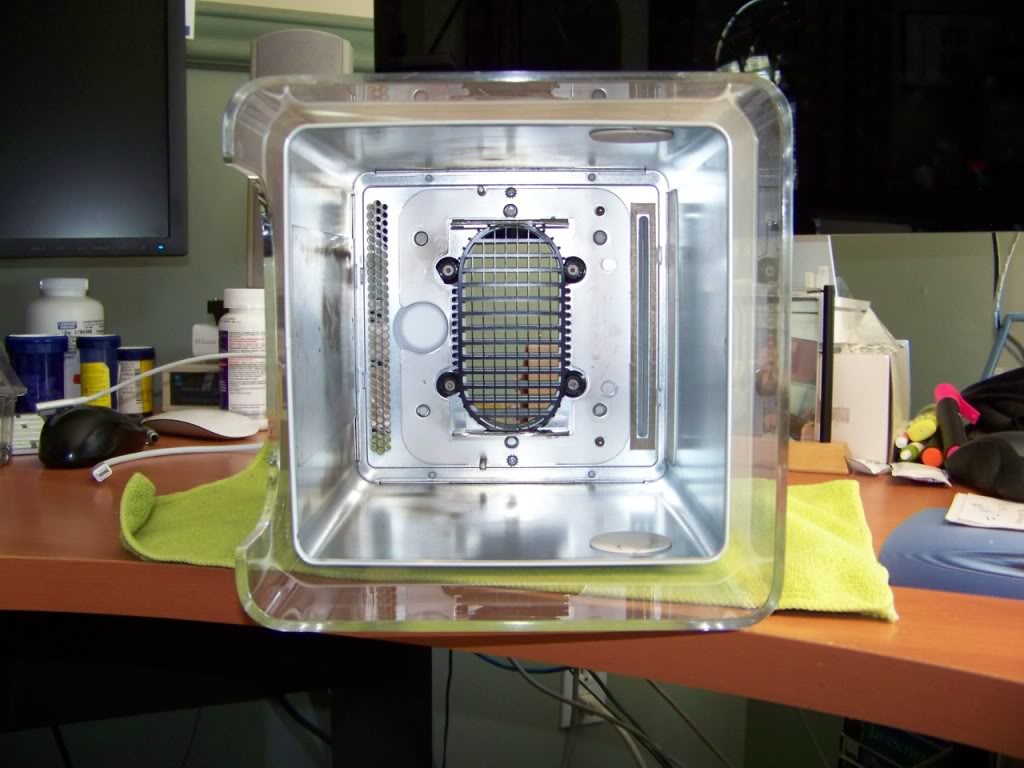
I removed the security lock, causing deep scratches to the side of the cube in the process. So I took an orbital sander to it an sanded out the scratch. The cube looked frosted! I then used the 3 step Novus polish and, boy does that stuff work!
Here is the end result:
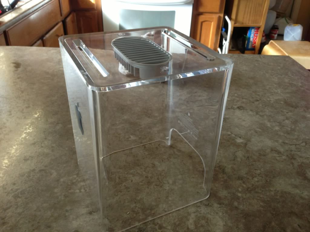
That stuff will get ANY scratch out!
Here is the end result:
That stuff will get ANY scratch out!
Last edited:
- Joined
- Jun 11, 2012
- Messages
- 355
- Motherboard
- GA-Z87X-UD3H
- CPU
- i7-4770K
- Graphics
- GTX 960
- Mac
- Classic Mac
- Mobile Phone
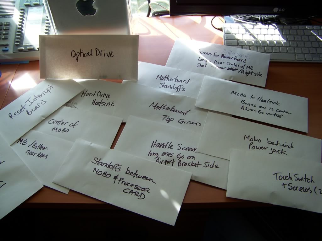
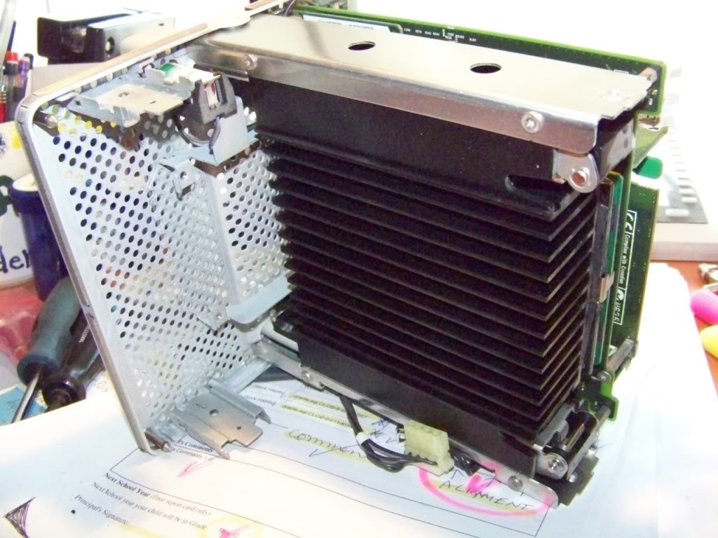
Teardown
Since I was disassembling a working cube that I was going to use for parts, I grabbed a handful of envelopes and every time I took something apart, I put the screws in an envelope and wrote on the envelope where they came from. That made it much easier to reassemble the cage after the teardown was complete.
The only parts I intend to keep for the build are:
- Top Plate
- Bottom Plate
- 4 Corner Posts
- Drive Cage
- Handle
- Plastic Hard Drive Guide/Slide
- Latching Struts and the left and right sides of the heat sink.
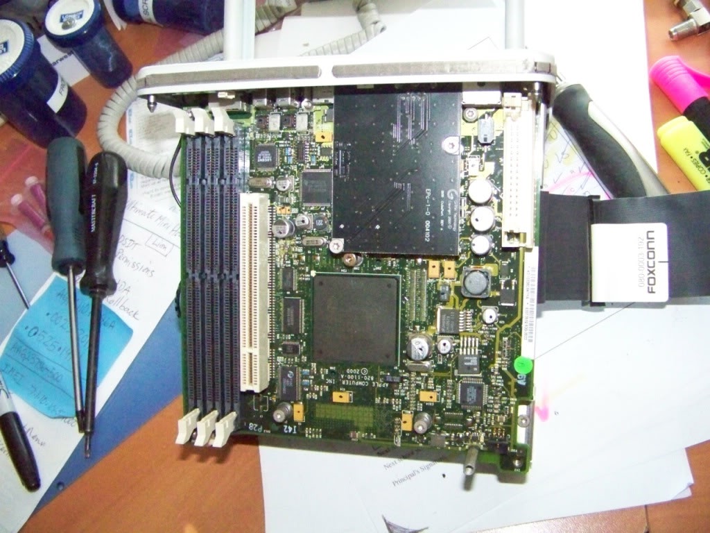
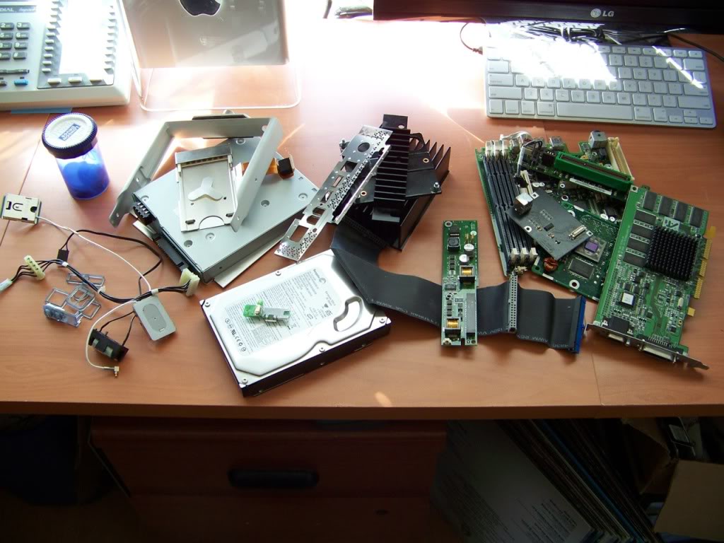
Here are all the parts Im not going to use.
Since I was disassembling a working cube that I was going to use for parts, I grabbed a handful of envelopes and every time I took something apart, I put the screws in an envelope and wrote on the envelope where they came from. That made it much easier to reassemble the cage after the teardown was complete.
The only parts I intend to keep for the build are:
- Top Plate
- Bottom Plate
- 4 Corner Posts
- Drive Cage
- Handle
- Plastic Hard Drive Guide/Slide
- Latching Struts and the left and right sides of the heat sink.
Here are all the parts Im not going to use.
Last edited:
- Joined
- Jun 11, 2012
- Messages
- 355
- Motherboard
- GA-Z87X-UD3H
- CPU
- i7-4770K
- Graphics
- GTX 960
- Mac
- Classic Mac
- Mobile Phone
Planning
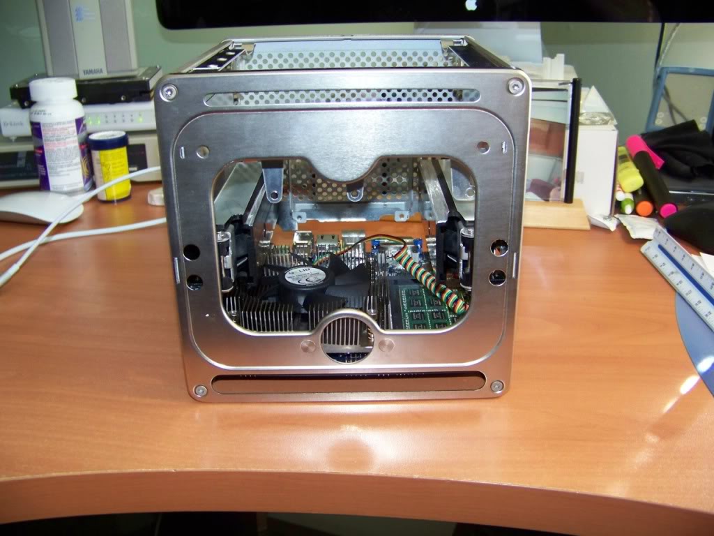
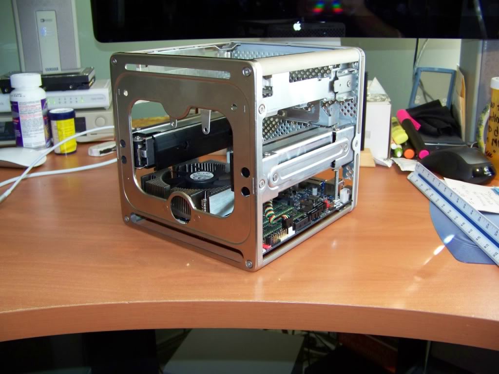
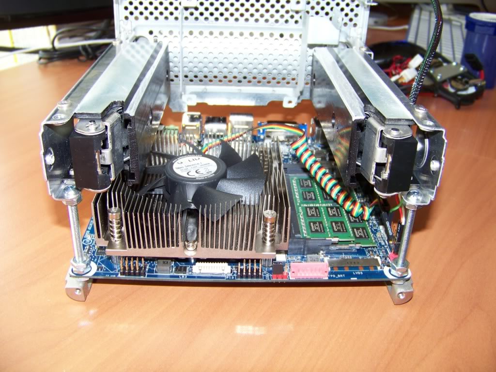
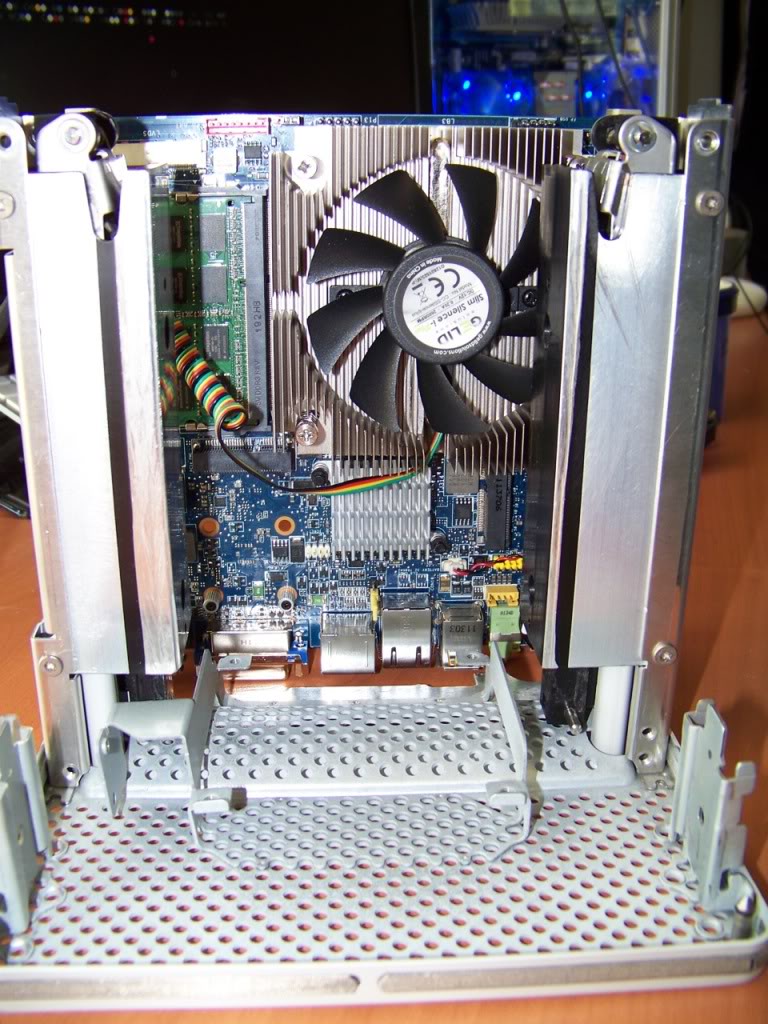
I studied all the cube mods on this site. All were done slightly different, with different components and different goals in mind etc. They are all GREAT! And a fantastic resource for a first time cube modder! I decided that I wanted to keep the drive cage and use it to mount two 2.5" drives instead of a single full size drive. I will use a dual 2.5 to 3.5 drive adapter bracket for this. I plan to mount the motherboard in generally the same place as the original; to the rear of the case, and the components will be facing inwards. I plan to cut out the center part of the heatsink to add more room for airflow. This will give lots of room for the cpu cooler to do its work. I plan to install a low profile 80mm fan at the bottom where Apple conveniently placed a mounting bracket. I will place two 40mm fans near the top, just below the grille. This should create a push-pull scenario that should provide adequate cooling and ventilation.
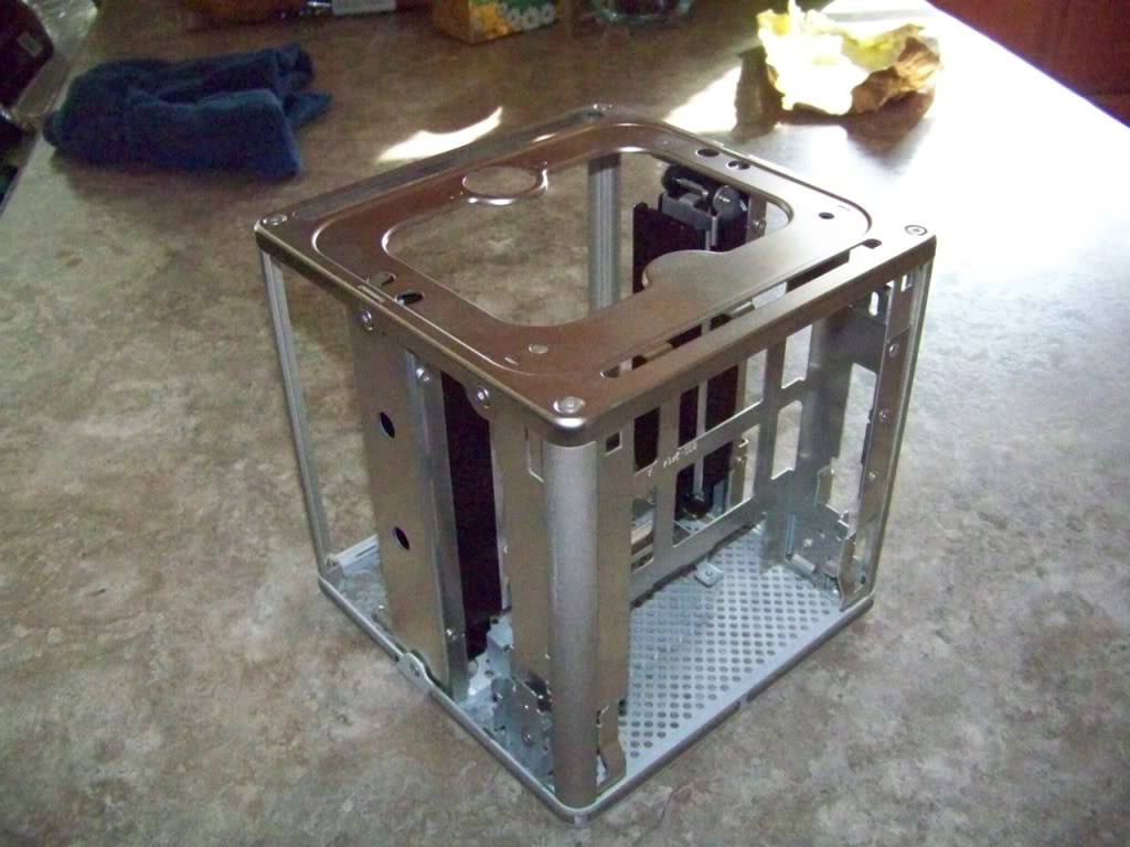
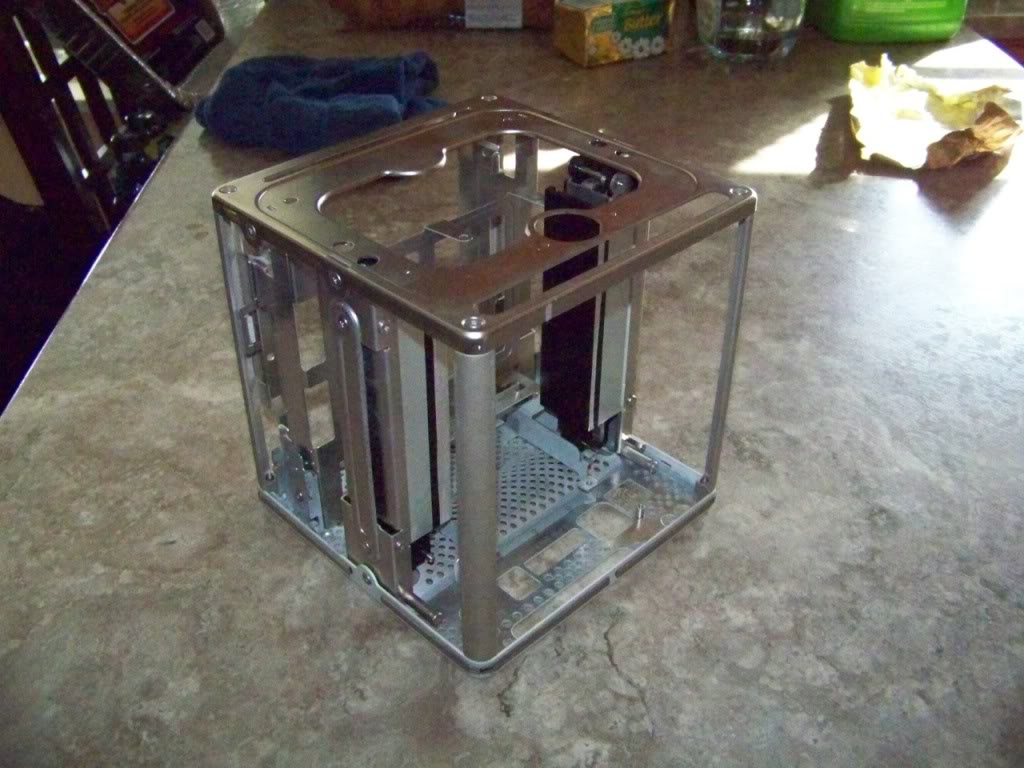
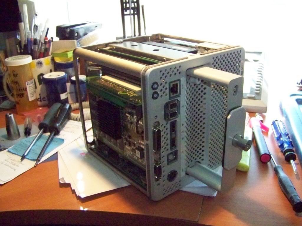
All the chassis parts I intend to use, assembled.
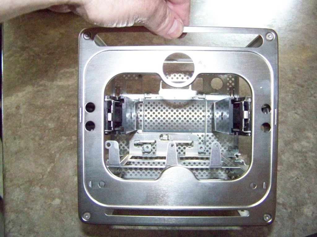
I stared at this for hours, visualizing where everything will go. One needs to keep in mind that the top grill hangs down into the cube top area.
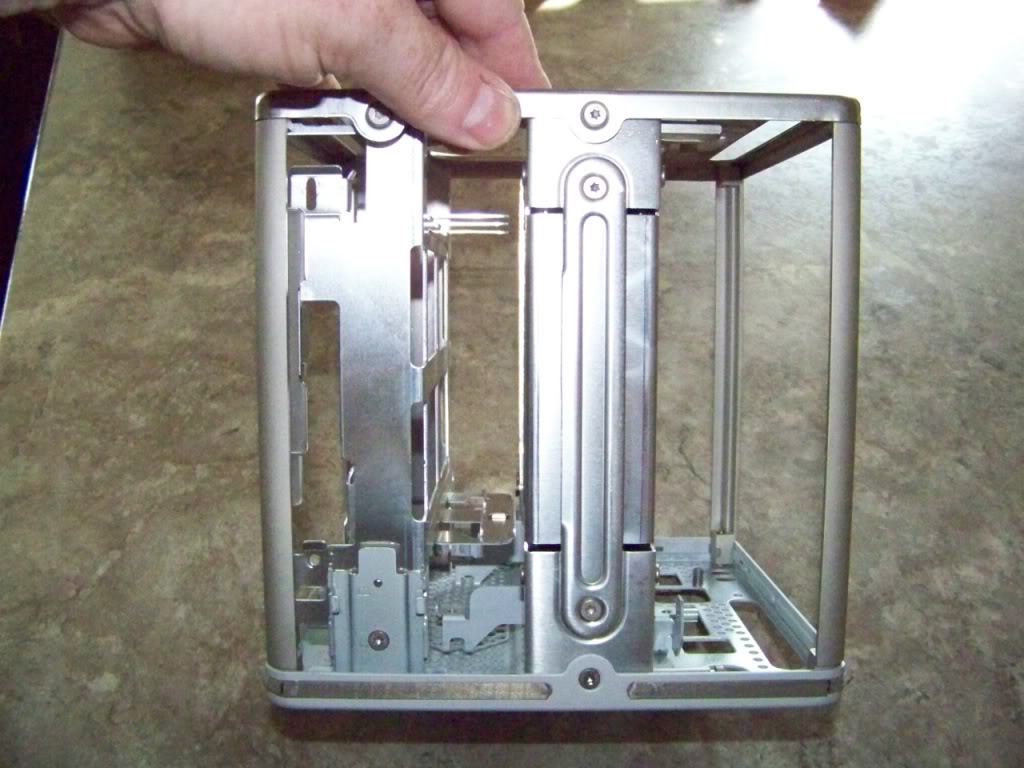
Note: I cut the hinge and Airport card tray off. I will be using the wire retainer. Also note that I switched around the two latching struts. This helped me in two ways; 1) the wire retainer now falls on the correct side of the motherboard for retaining the power and SATA cables, as well as USB and power, etc. and 2) It puts the original motherboard support holes on the opposite side leaving this side clear metal to drill holes into (where the mITX layout requires) for motherboard supports.
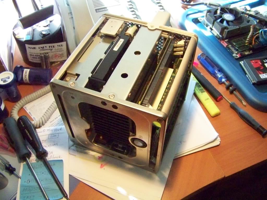
Shows where my drives will slide in.
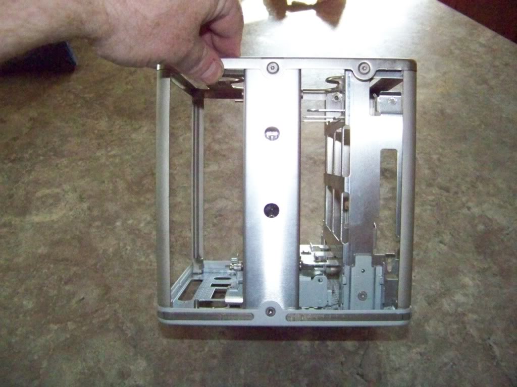
There is actually quite a lot of room in there once the heatsink is removed. The top grill occupies the center area from the top of the struts, upward.
I studied all the cube mods on this site. All were done slightly different, with different components and different goals in mind etc. They are all GREAT! And a fantastic resource for a first time cube modder! I decided that I wanted to keep the drive cage and use it to mount two 2.5" drives instead of a single full size drive. I will use a dual 2.5 to 3.5 drive adapter bracket for this. I plan to mount the motherboard in generally the same place as the original; to the rear of the case, and the components will be facing inwards. I plan to cut out the center part of the heatsink to add more room for airflow. This will give lots of room for the cpu cooler to do its work. I plan to install a low profile 80mm fan at the bottom where Apple conveniently placed a mounting bracket. I will place two 40mm fans near the top, just below the grille. This should create a push-pull scenario that should provide adequate cooling and ventilation.
All the chassis parts I intend to use, assembled.
I stared at this for hours, visualizing where everything will go. One needs to keep in mind that the top grill hangs down into the cube top area.
Note: I cut the hinge and Airport card tray off. I will be using the wire retainer. Also note that I switched around the two latching struts. This helped me in two ways; 1) the wire retainer now falls on the correct side of the motherboard for retaining the power and SATA cables, as well as USB and power, etc. and 2) It puts the original motherboard support holes on the opposite side leaving this side clear metal to drill holes into (where the mITX layout requires) for motherboard supports.
Shows where my drives will slide in.
There is actually quite a lot of room in there once the heatsink is removed. The top grill occupies the center area from the top of the struts, upward.
Last edited:
- Joined
- Jun 11, 2012
- Messages
- 355
- Motherboard
- GA-Z87X-UD3H
- CPU
- i7-4770K
- Graphics
- GTX 960
- Mac
- Classic Mac
- Mobile Phone
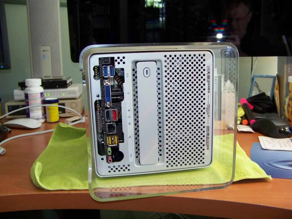
Mounting the motherboard and cutting the bottom plate
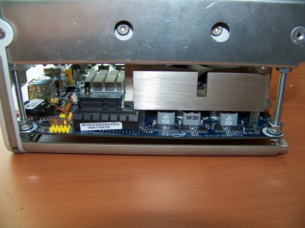
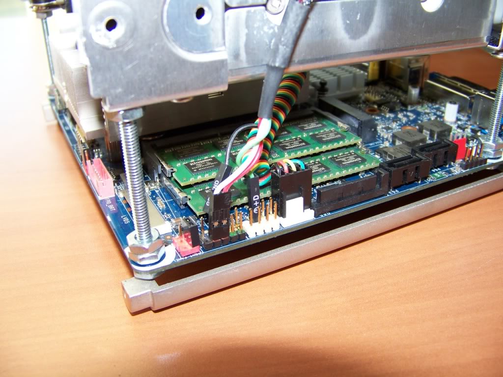
The motherboard should be as far back as possible..it needs to be 1.5 mm away from the corner posts as it needs nearly the entire width of the cube. I will need to mount it as low as possible, perhaps 0.5mm away from the bottom plate. I decided that the corner posts did not make a stable enough mounting surface as they are only placed on pins and screwed at the top. Also, they didn't look like they would respond well to drilling and tapping. I decided to use a long bolt and a series of nuts and mount the motherboard from the component side to the center struts. I used 3" bolts and cut them down to the correct size with the dremel. I also cut the extra screw mount and the wire holder off of the bottom fan bracket. I removed the struts lined them up with the motherboard and marked and drilled them for the bolts. I fed the bolt through the holes and tightened them down with a nut on each bolt, tight up against the strut brackets. I then added two nuts onto each "standoff" and positioned them where I wanted the board to sit. I then tightened them against each other creating a platform for the motherboard. I placed the motherboard onto the four standoff's and put four final nuts, one on each standoff on the underside of the motherboard.
I then had the motherboard and the two struts as an assembly that could slide onto the "fingers" on the baseplate.
It was time to cut the baseplate. In order to have the motherboard sit in its correct position, some of the I/O needed to protrude through the baseplate. I lined up the struts on the fingers and slid the assembly so the I/O touched the baseplate. With the board in that position, I marked the bottom of the baseplate for cutting to remove just enough material so that all the I/O connectors would protrude appropriately. I wanted the motherboard to sit a fraction of a mm above the baseplate. I will measure and cut the final opening for I/O shield later, but for now, I wanted to finalize the position of the motherboard.
I then cut the baseplate opening using my dremel. I noticed with my G5 mod that as you use the cutting disks they get smaller. I also noticed that it is very difficult to get into tight corners with new, fresh, disks. So when my disks wear down to about 10mm in diameter, I take them off and save them for when I need to get into a tight corner. Large disks are better for long straight cuts, anyway.
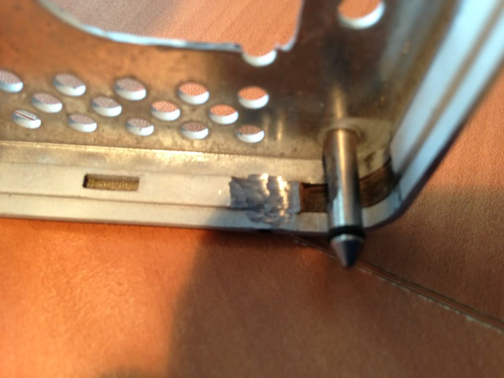
I cleaned off the baseplate and then began to attach the struts-motherboard assembly to it by again sliding it onto the fingers. When I did this, I noticed that the lowest standoff needed a bit of grinding off of one side of the bolt head in order to slide nicely on the baseplate fingers on the one side. Also, there is a 1mm ridge on the inside lip of the baseplate... I had to grind that off of both sides where the edge of the motherboard comes in contact with the baseplate. Less than 0.5mm of material was removed with the dremel, and the board slipped nicely down to the bottom of the plate. I screwed the struts into the fingers.
Here is where I ground off a small ridge on the inside lip of the base plate:
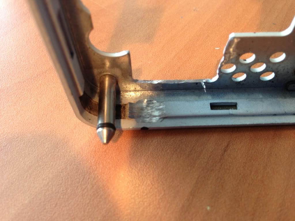
and here:
Here is a shot of the bottom with the motherboard mounted.
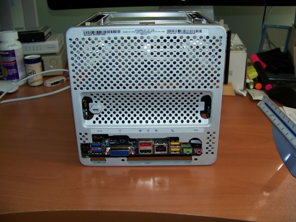
Side view:
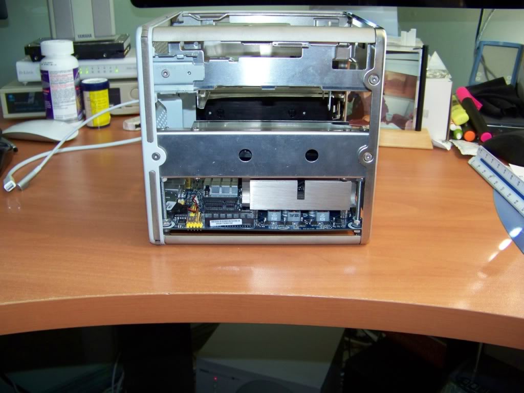
Top View:
Top and other side:
The motherboard should be as far back as possible..it needs to be 1.5 mm away from the corner posts as it needs nearly the entire width of the cube. I will need to mount it as low as possible, perhaps 0.5mm away from the bottom plate. I decided that the corner posts did not make a stable enough mounting surface as they are only placed on pins and screwed at the top. Also, they didn't look like they would respond well to drilling and tapping. I decided to use a long bolt and a series of nuts and mount the motherboard from the component side to the center struts. I used 3" bolts and cut them down to the correct size with the dremel. I also cut the extra screw mount and the wire holder off of the bottom fan bracket. I removed the struts lined them up with the motherboard and marked and drilled them for the bolts. I fed the bolt through the holes and tightened them down with a nut on each bolt, tight up against the strut brackets. I then added two nuts onto each "standoff" and positioned them where I wanted the board to sit. I then tightened them against each other creating a platform for the motherboard. I placed the motherboard onto the four standoff's and put four final nuts, one on each standoff on the underside of the motherboard.
I then had the motherboard and the two struts as an assembly that could slide onto the "fingers" on the baseplate.
It was time to cut the baseplate. In order to have the motherboard sit in its correct position, some of the I/O needed to protrude through the baseplate. I lined up the struts on the fingers and slid the assembly so the I/O touched the baseplate. With the board in that position, I marked the bottom of the baseplate for cutting to remove just enough material so that all the I/O connectors would protrude appropriately. I wanted the motherboard to sit a fraction of a mm above the baseplate. I will measure and cut the final opening for I/O shield later, but for now, I wanted to finalize the position of the motherboard.
I then cut the baseplate opening using my dremel. I noticed with my G5 mod that as you use the cutting disks they get smaller. I also noticed that it is very difficult to get into tight corners with new, fresh, disks. So when my disks wear down to about 10mm in diameter, I take them off and save them for when I need to get into a tight corner. Large disks are better for long straight cuts, anyway.
I cleaned off the baseplate and then began to attach the struts-motherboard assembly to it by again sliding it onto the fingers. When I did this, I noticed that the lowest standoff needed a bit of grinding off of one side of the bolt head in order to slide nicely on the baseplate fingers on the one side. Also, there is a 1mm ridge on the inside lip of the baseplate... I had to grind that off of both sides where the edge of the motherboard comes in contact with the baseplate. Less than 0.5mm of material was removed with the dremel, and the board slipped nicely down to the bottom of the plate. I screwed the struts into the fingers.
Here is where I ground off a small ridge on the inside lip of the base plate:
and here:
Here is a shot of the bottom with the motherboard mounted.
Side view:
Top View:
Top and other side:
Last edited:
- Joined
- Sep 22, 2010
- Messages
- 26
- Motherboard
- ASUS MAXIMUS X HERO (WIFI/AC)
- CPU
- i7-8700K
- Graphics
- RX 580
- Mac
- Mobile Phone
Mounting the motherboard and cutting the bottom plate
I decided to use a long bolt and a series of nuts and mount the motherboard from the component side to the center struts. I used 3" bolts and cut them down to the correct size with the dremel.
Thanks for the write up. This is how I envisioned I would mount the motherboard when I mod my G4 Cube.
I'll be watching this thread. Great work!
Alan
- Joined
- May 27, 2010
- Messages
- 2,364
- Motherboard
- Dell Optiplex 9030 All in One
- CPU
- i5-4690K
- Graphics
- HD 4600
- Mac
- Classic Mac
- Mobile Phone
Very neat job and a nice write up. Looks very familiar to some of the stuff on my last mod....so are you going to use the touch switch at the front? Looks like you should have freed up enough room for that..

- Joined
- Jun 11, 2012
- Messages
- 355
- Motherboard
- GA-Z87X-UD3H
- CPU
- i7-4770K
- Graphics
- GTX 960
- Mac
- Classic Mac
- Mobile Phone
Here are some extra photos.
Last edited:
- Joined
- Jun 11, 2012
- Messages
- 355
- Motherboard
- GA-Z87X-UD3H
- CPU
- i7-4770K
- Graphics
- GTX 960
- Mac
- Classic Mac
- Mobile Phone
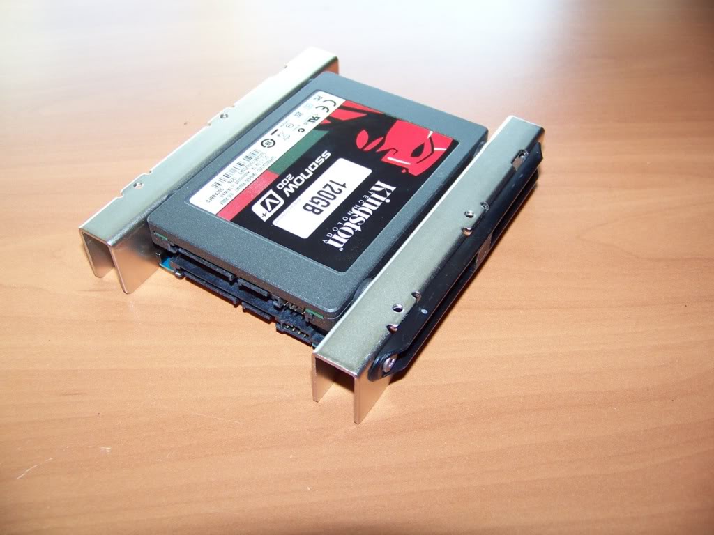
Mounting the Hard Drives
Mounting the drives was pretty straightforward due to the adapter brackets I bought and the fact that I planned to re-use the original hard drive mounting location. The only issue was orientation. When the drives were mounted with their connectors on the left side the SATA connectors protruded past the cube's frame. Since the drives are stacked, I could not use 90 degree connectors; I had to use the straight connect ones.
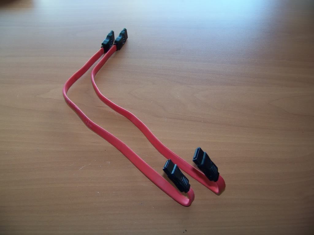
I used two spare cables that I had lying around as they were shorter than the ones that came with the motherboard.
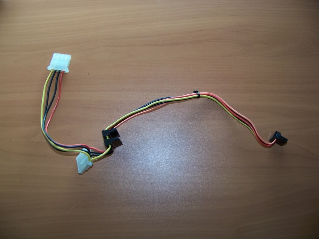
I didn't want bunches of cables all over the place so I made my own power cable using a spare ATX pigtail and some SATA power connectors. The two extra Molex connectors are for fans and accessories.
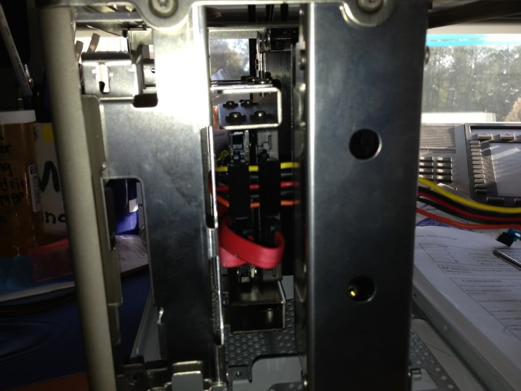
This shot shows the connections to the drive...its a tight space.
Mounting the drives was pretty straightforward due to the adapter brackets I bought and the fact that I planned to re-use the original hard drive mounting location. The only issue was orientation. When the drives were mounted with their connectors on the left side the SATA connectors protruded past the cube's frame. Since the drives are stacked, I could not use 90 degree connectors; I had to use the straight connect ones.
I used two spare cables that I had lying around as they were shorter than the ones that came with the motherboard.
I didn't want bunches of cables all over the place so I made my own power cable using a spare ATX pigtail and some SATA power connectors. The two extra Molex connectors are for fans and accessories.
This shot shows the connections to the drive...its a tight space.
Last edited:
- Status
- Not open for further replies.
Copyright © 2010 - 2024 tonymacx86 LLC