Contribute
Register

My PowerHack G5 build

Status
Not open for further replies.
Joined
Nov 27, 2013
Messages
8
Motherboard
GA-H97M-D3H 9 series
CPU
i5-4670
Graphics
Saphire Radeon R9 270X Dual-X OC 2GB
Mac
  1. Mac Pro
Mobile Phone
  1. iOS
Hello,

Please forgive my English - I am not native speaker.

Two weeks ago my Haswell Hackintosh decided to commit suicide by burning CPU and mobo. I found I had a lot of spare time having no computer at home, so I decided to rebuild my Hackintosh with brand new look. I decided as well to change some ideas compared to my original build (Z87N-WIFI mITX). In general new build should sort out two main problems - lack of PCI/PCIe slots, as I had to swap my Firewire card with GeForce to play games/record music using audio iface, and the second - loud vibrations caused by cooling pump as Zalman LQ-310 was too "loud" when recording guitars :) .

I decided to go with PowerMac G5 case as it looks ... just great.

Spec:
Motherboard:
Gigabyte H97M-D3H MicroATX
(I bought 9 series as ... I could not find any Z87/H87 in Ireland anymore. I am not sure if it was good decision yet .... I will see after buying CPU that can run 10.9.x)

CPU:
Intel Celeron G1820 .... yeahh I know... speed demon and yeahhh ... not compatible with 10.9.x - it will be replaced soon to Intel Core i5-4670 as on my original build was.

RAM:
Corsair Vegenance LP 2x 8GB

GFX:
Gainward Geforce GT640 1GB DDR5

HDD:
1. Seagate Barracuda 2TB (for data only HFS+)
2. WD Caviar 500GB (NTFS for Windoze)

SSD:
Samsung 840 Evo - 240GB (for OSX)

PSU:
XFX XTR 550W ( it is rebranded Seasonic G as far I know - 80+ gold with hybrid mode )

Cooling:
Case - 120mm fans from my old case (Scythe Glidestream and some CoolerMaster)
CPU - Arctic Cooling Freezer Pro 7 rev2 (will install it after buying i5 - no point to use it for Celeron)

Optical drive:
None yet - I had slot loading slim type drive in old build, but as I want to leave original G5 bay cover I will need to buy "normal" dvd writter .

No sponsors, No links to amazon etc..... the only cause of this build is Intel as they sold me my original faulty CPU and online computer part shops in Ireland that do not have H87N-WIFI in stock anymore.
HDD,SSD, GFX , RAM and PSU are from previous build. Only new parts are CPU , mobo and G5 case.

I am going to put photos of new build very soon....

Day 1. "Shopping" - I found two guys in Ireland selling broken G5s. I decided to buy both and use the case that will be in better condition. One is after cooling system leak and second one after flood :eek: (both damaged by liquids) Cost of both .. 45 euro (about $60)

1.JPG
 
My goodness you got a deal!!!:clap:
Did you feel guilty when you drove off for stealing those cases, I would have. :lol:
Now!!!
Get ir done:thumbup:
 
Actually at this moment I am almost finishing this mod, all things I am going to post here is a log from last couple days that I spent on this.

First I've read all articles inside .... tonymac's forum about G5 case mods :) Then I made some important decisions:

1. PSU on top of case in place of hdd caddy
2. No ready-made elements like backplate, fan holders etc.
3. Use original PCI slot locations and mobo standoffs
4. Do not mod external look :) (at the moment)
5. Use Epoxy to mount mobo stand-offs - also use original stand offs
6. Make it look ... nice.... inside
7. Do everything with tools I have in my garage ... pretty limited - just a drill, jigsaw (but have no blade for metal) and "dremel" like tool... some manual tools as well :)
8. Reuse all rubish I found in my garage ... like old arylic sheet, Ikea backing tray, car speaker cables, cable ties :D
9. All front panel sockets must be operational.


Day 2. Cleaning

I found both of cases were extremely rusty at the bottom - the power supply metal box looked like parts of Titanic on underwater videos. So I started to disassemble all elements... finally I cleaned all rust using mix of water and vinegar and then done some sanding.


This is after first small cleaning - still some rusty spots
2.JPG
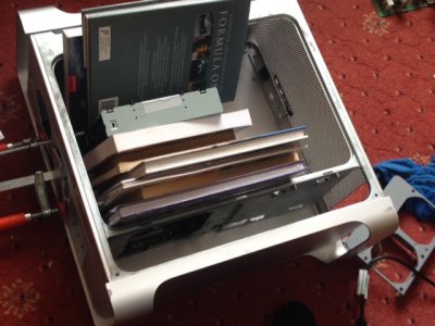
Dissemble in progress
1.JPG
3.JPG
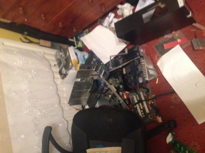
And ... finally both cases empty ... Here are all parts removed - 2 mobos, cpus, psus ....What a mess !!
5.JPG


Day 3 - Power supply mount and stand offs

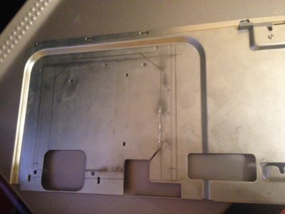
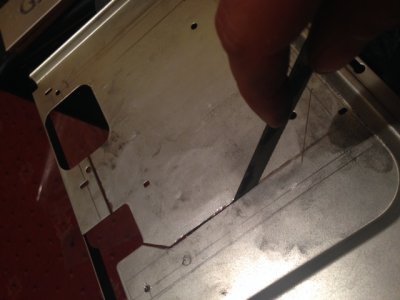
As I decided to mount PSU on top shelf I needed to mod it to have a cutout for PSU fan and holes to screw it into shelf. As my jigsaw does not have a blade for metal I decided to cut it manually using just metal saw and file: Here is a result :) I put old Pentium 4 mobo as reference for standoffs height. As measured I file down standoffs to 12mm. Third picture - first try if everything will fit as should.

1.JPG2.JPG3.JPG
 
I am back from my Holidays, so the story continues.

Day 4 - Acrylic Parts + PSU power cable

I decided to create support for fans using some 3mm acrylic that I found in my garage. As I found similar idea somewhere on the network I just copy it. I decided also to put back original PSU box to the case and create extension from original location of the power socket to upper shelf. Also instead of metal shield that was installed on top of original PSU I cut out some acrylic to cover PSU box.

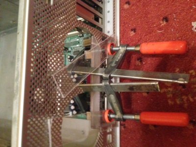
Here is a finished fan holder for front of the case. Some acrylic with cutouts. I used heat gun to bend it and then made holes for screws.
zdjęcie 1.JPG zdjęcie 2.JPG

The next acrylic part is the IO shield for motherboard. I cut out the back of original case using dremel tool. The frame is made of the same acrylic, but I used some black spray paint to make in non translucent. I used some super glue to join all the parts together and small screws to screw the frame to the case. Installing it with proper alignment was a difficult task as the frame goes "little bit" over PCI bottom of PCI slot 1, so I had to remove that nice plastic frame with 1234 marks and make more room for frame by cutting bottom of the metal from PCI slots and then mount back the plastic with slot numbers. Finally everything matched perfectly.

zdjęcie 4.JPGzdjęcie 3.JPG

Day 5 - Standoffs glue and back plate.

On next day I decided to finally use Epoxy to glue down motherboard standoffs. And here I need to tell. The epoxy I used (Araldite Metal/Aluminum Glue) is .... crap. I glued the standoffs three times, as everytime I installed motherboard they just broke. After three times I finally decided that 2 loose standoffs will not make a huge difference and it might be enough to support the motherboard. As I see I also relocated hdd caddy to the bottom of optical drive.
zdjęcie 1 (1).JPGzdjęcie 4 (1).JPG

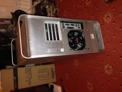
The next challenge was a back plate. I used gray backing tray that I bought in IKEA :) Same as top shelf I used some metal saw and a lot of dremel bits to cut out holes for io shield and fan. Finally everything looks like on pictures
zdjęcie 2 (1).JPGzdjęcie 3 (1).JPG

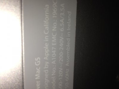
Also ... I found funny thing ... Power Mac G5 ... "Assembled in Ireland" ... yeahh ... Once again it is assembled here :)

zdjęcie 5.JPG
 
screemer thank you for sharing your project on the forum. I do like the motherboard install at the rear panel reusing the existing PCI slots and the rear panel plate that you fabricated.

More photos of the finished project once you are up and running in your intended confirmation would be nice.

Good modding,
neil
 
Day 6 and 7 - Details /Final build / Front Header

As I planned from the beginning the case interior should be black (without any led lights at the moment). I bought 3M "carbon look" vinyl wrap on ebay and wrapped all arcylic parts and back of the case. Also I painted top shelf using glossy black car paint spray.

zdjęcie 1.JPG

In general .... it looks much better than on photo that were taken in the evening. I will try make better photos when everything will be finished. The next step was to install all the hardware. Good news was that Intel sent me back brand new i5 cpu and it arrived just on time when I finished all major parts of this modification. I installed all parts ... mobo, cpu, ram, gfx and my firewire controller. Also I used additional header for 4xUSB in one of PCI slots.

Then I started to work on front panel header. I wanted to have all sockets fully working... First thing I soldered was a extension cable for firewire and connected it to internal fw port on controller (this is TI based card fully supported by osx). Then I put two cables for power led and power button. The schematic of front panel header found here on forum gave me the idea that they both user same ground wire ... and that the FW voltage is doubled to 24V ... I used the schematic from this post

http://www.tonymacx86.com/powermac-g5/106061-my-first-case-mod-g5.html

and realized ... it is not working on my mobo as expected. I do not know if schematic is wrong, or just my mobo does things differently.
First ... the voltage of Firewire hot pin (pin 1) has to be just +12V not +24V -everything works (tested with my FW audio recording interface that is powered by firewire ). This is actually really good news, as in ATX PSU there is no 24V line. The only problem is that in genuine Apple computers voltage on firewire port is always on, but on ATX standard in sleep states S3 , S4 and S5 (deep sleep and shutdown) +12V line is disconnected and only low power 5VSBY line is available. At this moment I am happy not to fix this problem as I can just press power switch on my audio interface, but .. if someone wants to have same functionality as on real mac I found schematic using simple DC-DC converter here :

http://www.sinus-electronic.de/datenblaetter/aic/an00-009.pdf

This is not tested... but I think may do the job.

Second ... the schematic of power button and led is not working with my motherboard. It is stated there that power button and led uses same Firewire Ground signal that is actually true ... but not on my motherboard. Power button wiring is actually OK, so connecting pin 13 and 2 to motherboard PWR pins works ... but ....POLARITY is very important ... and it is not clearly stated on motherboard where is + and - on PWR header. if you put the cable "upside down" it will ... act as power button pushed permanently (computer will constantly switch on and off). This is just advice for new builders.
Another story is the LED ... When I connected the led as found here ...

http://www.tonymacx86.com/members/a...ase-mod-g5/63976-g5-front-wanel-w-jumpers.png

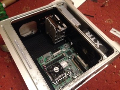
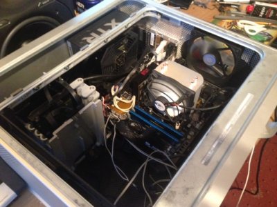
The LIGHT was ALWAYS ON in every ACPI state - even when computer was switched off !! This problem exists because the PC motherboard is driving LEDs (both PWR and HDD) by grounding negative lines that are normally attached to +5v in standby mode !!!. This is totally different that I was expecting after reading the post I just mentioned above. In general when Power is On and computer is ON line "-" on PWR LED header (Or HDD led as they work exactly the same) on mobo is 0V and "+" is +5V (also I found there is 100 Ohm resistor inline to limit current on leds), but when computer is switched off ... here is the surprise .. "-" is +5V and "+" is also +5V. The led is not light as there is no voltage difference. When we ground the led on header as it is done in Apple design ... it will always lit !! The solution I decided to use is to drive the LED using small converter of motherboard signal to drive original G5 LED with usual +5V switching. The schematic is very easy ... it needs just one optoisolator chip and resistor. I used commonly available and very cheap 4N35 chip. Pinout is easy ... pin 1 and 2 on chip goes to PWR LED + and - on motherboard (as motherboard has got already current limit resistor we do not need anything else). Pin 5 is collector - so it needs to be connected to +5V (for example "stolen" from one of USB headers). And then pin 6 is emitter so I soldered 100 Ohm resistor to this and the other leg of resistor finally goes to Apple's header pin 14. This solution JUST WORKS ... also it works even when connected to HDD led. I am thinking about another upgrade of this idea to use G5 power led for both power and hdd signals different brightness levels ... As all that reverse engineering took some time I did not finish soldering USB and Audio connectors yet. But I finally powered the computer and installed Win7 on one of hard drives - full success (as you see on the picture ssd was not yet installed at that time, same for optical drive). Also I found that cooler on the back of case is to noisy (broken bearing) and will need to be replaced. - Next post will describe a little bit of osx installation ... that I finally started yesterday ... just to let you know 10.9.0 is now on ssd and is booting, but no audio gfx or ethernet yet as I did not have time to install multibeast yet. Here is a photo of first power on :)


zdjęcie 2.JPG
 
Day 8 and 9 - Installation

Good news .... Maveriscks works absolutely perfect. I did the installation little upside down. I had only 10.9.0 app on my macbook and decided to use this one as my broadband is really slow, also my flash drive died so I decided to use old 2.5" sata hdd with usb enclosure.

Problem ... new Unibeast 4.x does not work with harddrives :( It needs so called "removable device". I had to use legacy Unibeast 3.x version. I prepared my installation device and run the installer from that external hdd. No chameleon flags ... just plain boot did the job - also no problem with first boot from hdd . After installation I logged to AppStore and started all updates to 10.9.4 ( still without multibeast ). Update done without any problem. Then I installed latest Multibeast for mavericks 10.9.4 and ... problem occured. No configuration works on ALC drivers with 9 series (drivers based on applehda). No sound and no devices found using this kext - no luck with any setting in "Chimera" HDAEnabler. I switched off the enabler using chameleon plist file and reinstalled multibest with VoodooHDA 2.8.4 that time ... but the system shown that the kernel module is corrupted and was not able to load VoodooHDA at all..l .. Finally I found 2.8.5 VoodooHDA zipped using our dear uncle Google .... and installed the kext with kext loader b7 ... that instantly fixed all my problems with audio. All audio sockets are now working, including green rear port for line out ... I use discrete gfx card and my igp is off in bios so I can not check hdmi audio, but anything else works as expected.

so:

OSX works, Audio works, Ethernet works, USB 3.0 works, Firewire card works, GF640 works. Early adopted G5 look and feel computer is finally done. I did not check iMessage yet (probably I will need to do usual hack with file inside extra folder).


Of course I still need to work on front panel connections and some small details... But everything is just flying at the moment :) .


Oh one more thing ... HDMI audio on GeForce is visible as HDMI and HDMI (with encryption) in VLC player. If I select second one it is crashing the kernel ... total freeze of the system. Do you have the same issue ? I do not remember having two possibilities of HDMI audio selection in my old system.
 
Day 10....

Finally I managed to make power led and front USB to work as I wanted. Here is schematic:
schemeit-project.png

In general ... front header led is used for both power and hdd indicator. If only power led should be lit the current is limited with 5 kOhm resistor in series with standard 100 Ohm. This gives nice dim on front panel led (I do not know characteristics of the led used by Apple on G5 case , 5kOhm is value I found using potentiometer) . When hdd is active the transistor inside optoisolator makes short circuit on 5kOhm resistor and total resistance is just about 100 Ohm - same as on standard PC motherboard and the led is fully bright. In this case there is no need for second LED for hdd indication. The circuit needs +5V for led powering that is taken from +5V line of USB header tha goes into front panl as well (red wire). Feel free to implement this on your mods :) I think it is much better than adding second 3mm LED for HDD indicator. The schematic is super easy to solder and I just soldered all parts directly to cables and used some black isolation tape to cover it.

EDIT: I still think about solution for audio header switching that is totally different than "Intel Azalia" header standard used on PC motherboards.

BTW: On Voodoo HDA drivers the microphone is not recording :( It is active in voodoo mixer and I hear microphone in speakers but no capture on Skype :(
 
Status
Not open for further replies.
Back
Top