Contribute
Register

My First Hackintosh & Cube!

Status
Not open for further replies.
I'm not sure anymore, but I believe, that the springs must be attached to the heatsink.

See here:
G4%20Cuble%20Cutout%20for%20Cable%20Retainer.jpg


MacTester
 
Hey All,
Thanks for your input on the heatsink/handles and the SSD. I'm going to relocate the SSD and I was able to cut the heatsink today and have put it in the handle assembly. I've also finished retrofitting the old DVD drive to house the new one and have it mounted in the cube. My small exhaust fan is also in place.

As I'm looking at what others have done, many have had to tap holes for threaded motherboard standoffs either into aluminum blocks or the handle assembly itself. I don't have access to a tap, nor do I really want to purchase one just for this use. Do you guys think putting a nut on the end and j-b welding it to the handle assembly would be enough, or does anyone have another idea that doesn't involve a tap? I'd really want that to be a last resort.

Sadly I have to get somewhere and don't have time to post pics. Will do tomorrow. Thanks for all your help!

Cheers!
the simple way is to drill holes in the handle assembly, then simply put bolts through the holes and secure with a nut, no glue required, see photos in the following post. I did something similar in my build but used 40mm standoffs

http://www.tonymacx86.com/powermac-...d-case-mod-thawing-ice-cube-3.html#post468346
 
Thanks Kiwi! That got me thinking. I ended up using existing holes in the handle assembly, 3 from the original motherboard, and one that had priorly been apart of the handle assembly itself. The bolts aren't exactly straight, but they get the job done. I threaded them in and added J-B weld to be safe.

I now have everything in and ready except the SSD, touch button, and power/reset button. I will try to order the Edisen sensor tomorrow or Tuesday. Hopefully the wire transfer works out smoothly. As for the SSD, I took it out to relocate it and out of sheer curiosity decided to benchmark it for speed while it was out. After plugging it in with my SATA adapter it turns out this "New" SSD had files from a windows installation on it. So I'm going through the exchange process with Amazon. The new one should be here soon.

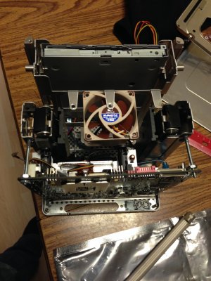
Here's some photos from the past couple days.

Photo Dec 29, 6 53 51 PM.jpg
J-B welded the fan it, and it worked great!
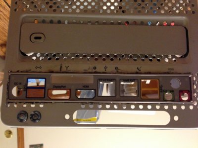
Photo Dec 29, 6 54 31 PM.jpg
After about an hour and a half of cutting and filing, got the I/O plat in...ended up I still needed to shift it to the left a bit. Didn't grab another picture of the bottom as J-B weld was setting, but it's not quite as perfect looking, but still not bad.
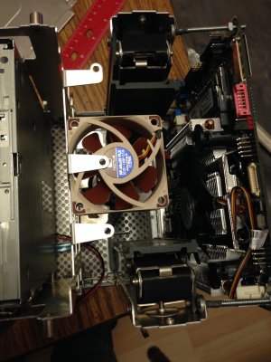
Photo Dec 29, 10 16 27 PM.jpg
Motherboard is in, with the DVD SATA hooked up as well as all the fans
Photo Dec 29, 10 16 38 PM.jpg
Top view of the current assembly
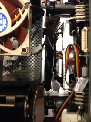
Photo Dec 29, 10 17 01 PM.jpg
The Silverstone AR-04 cooler fits in here AMAZINGLY well. There is plenty of room to work with and should cool the i3 nicely. The only con to it, and this may be just me, was that it was incredibly difficult to mount on the motherboard. Took some wrestling and pushing to finally get it on right.

So other than the power/reset switch it looks like I may have a day or two off. Which I am indeed ready for.
 
Hello All,
Sorry for the lack of posting, I'm saving up some funds to finish off the cube. What remains is both the physical power/reset button on the bottom and the touch sensor button on the top.

For the power/reset button I'm looking for something like this:
http://www.pololu.com/product/1015
for the header, and then using male to female jumper cables to make the connection to the motherboard.

For the touch sensor I was wondering if female to female jumper cables would work to take the leads of the sensor to the custom solutions header?

Does this sound reasonable? As I follow the pin diagrams from Ersterhernd.

Cheers!
 
Hi JD, you are making excellent progress! I applaud Polulu for their products. I order a whole whack of M/M F/M F/F pre-crimped wires, connectors, headers and pins from them every few months. It pays to have an assortment of options at your disposal when the modding gets serious. Also some assorted shrink tubing.

The custom solutions header is a smaller pin grid, not 2.54mm pitch like standard. I think it's a 2.0mm pitch, so you regular PC wires won't fit it. I used a front panel cable from a powerMac G5, it worked perfect as it fit the CS header like a glove. The CS header is buried inside the cube and tough to access, this cable really helped by extending it to a more accessible location.


Good Luck!
 
Status
Not open for further replies.
Back
Top