- Joined
- Jun 11, 2012
- Messages
- 355
- Motherboard
- GA-Z87X-UD3H
- CPU
- i7-4770K
- Graphics
- GTX 960
- Mac
- Classic Mac
- Mobile Phone
3) The Cutting Room: Mounting the Motherboard Tray
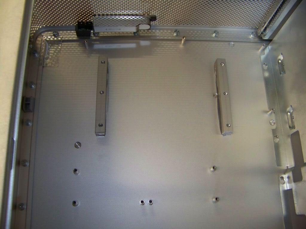
This was one of those “no turning back now” kind of things. I started by loosely assembling the Mountain Mods mobo tray. I want the top edge of the tray to be right up against the bottom of the top shelf.
I disassembled the MM tray and laid the MM back panel onto the back panel of the case lining up the top edge line. Now all I had to figure out was how far from the rear side it should be. That depended on where the tray sat on the standoffs. I plan to use those to secure the tray to the case.
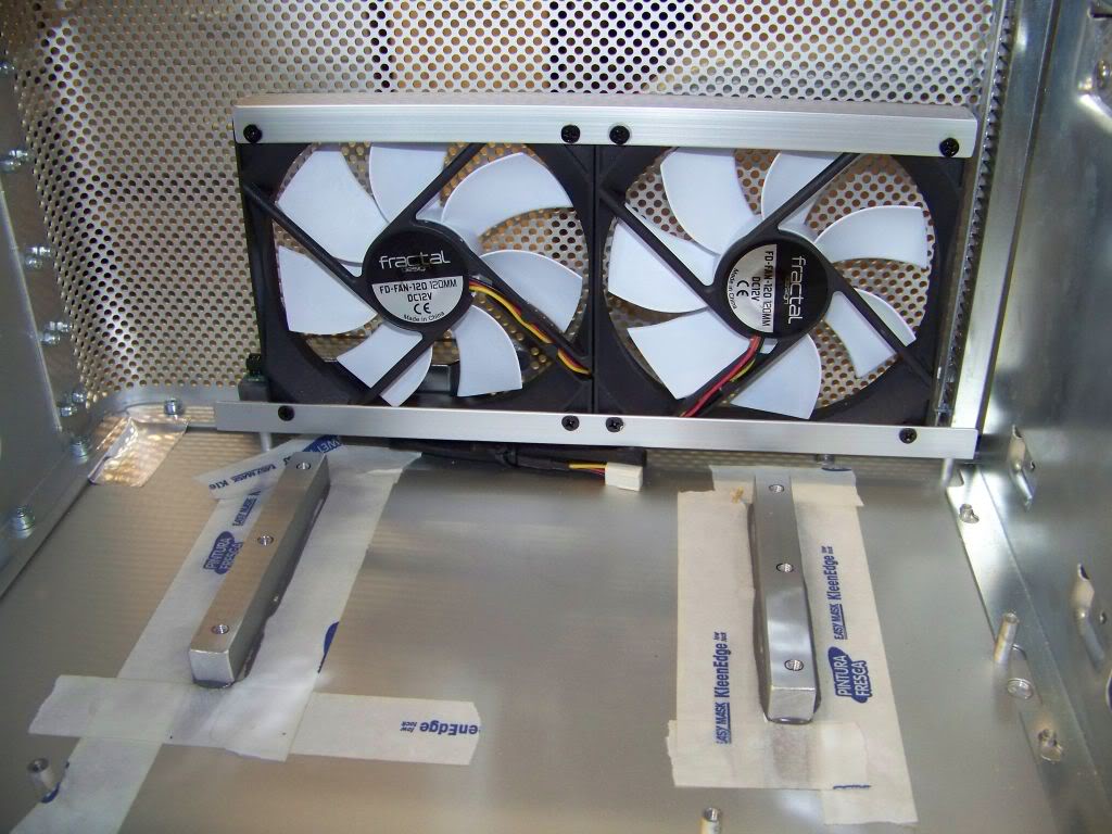
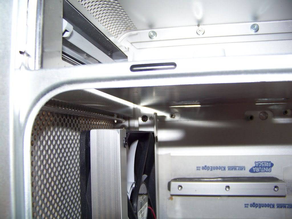
I then dry fitted things and marked where I needed to open some more space for MM back panel flanges and the 80mm fan bodies to sit nicely onto the back panel.


Once that was complete, I used my masking tape to help transfer the position of the standoffs to the MM tray and drilled holes so it could be mounted.

I also marked and cut out the part of the back panel that covered the case locking lever. Whew!
This was one of those “no turning back now” kind of things. I started by loosely assembling the Mountain Mods mobo tray. I want the top edge of the tray to be right up against the bottom of the top shelf.
- I transferred a measurement of the position of the bottom of the top shelf to the outside of the back of the case.
- I then measured from the edge of the MM tray to the top of the MM back panel and transferred that measurement to the back panel of the case.
I disassembled the MM tray and laid the MM back panel onto the back panel of the case lining up the top edge line. Now all I had to figure out was how far from the rear side it should be. That depended on where the tray sat on the standoffs. I plan to use those to secure the tray to the case.
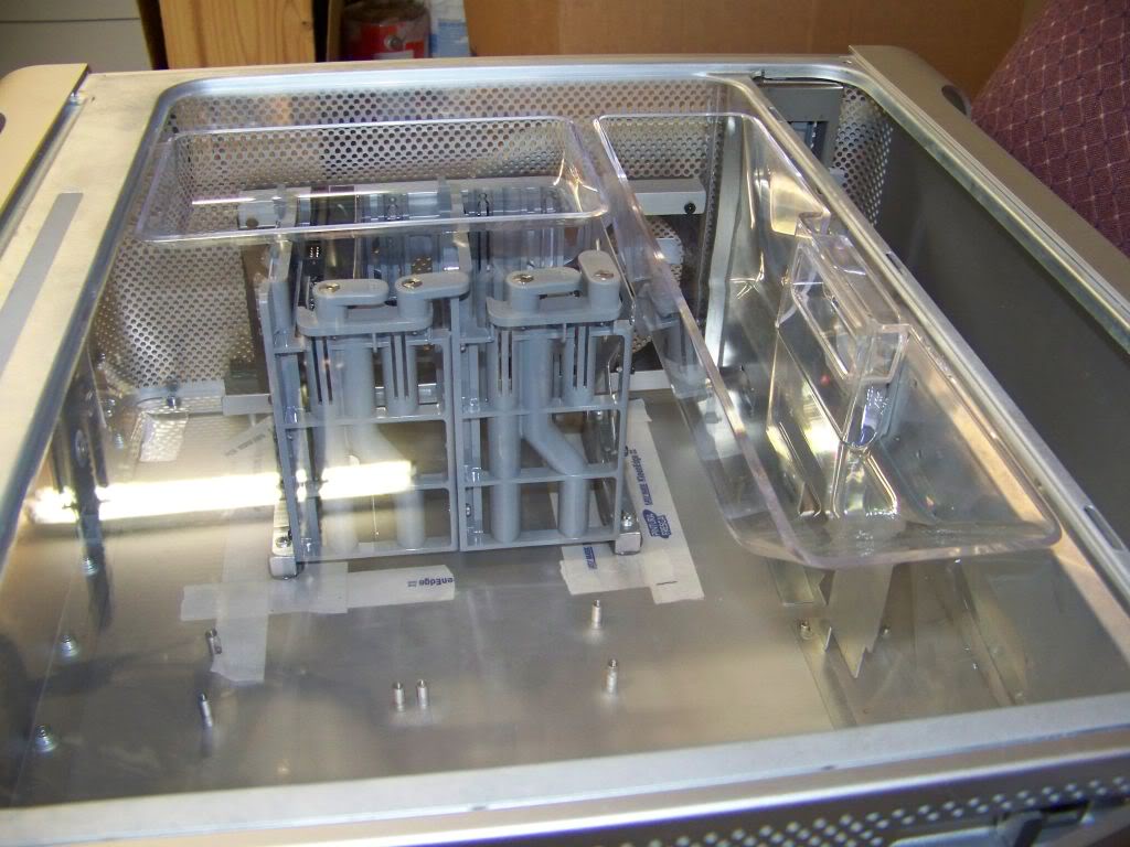
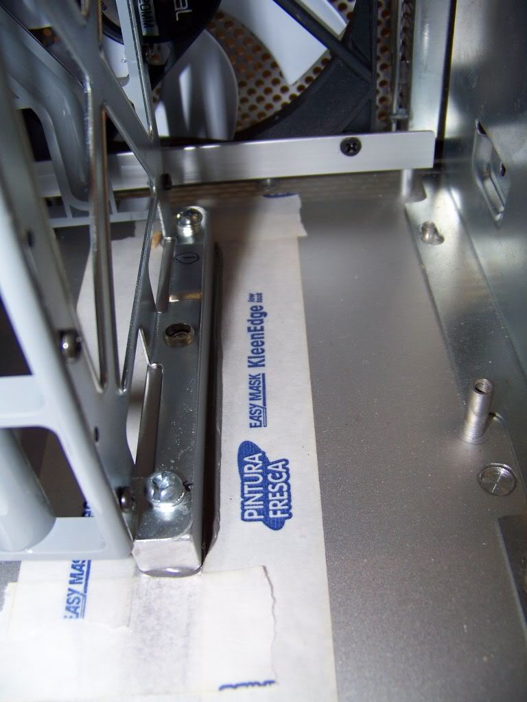
- I placed just the tray into the case positioned it up against the top shelf and as far back as possible.
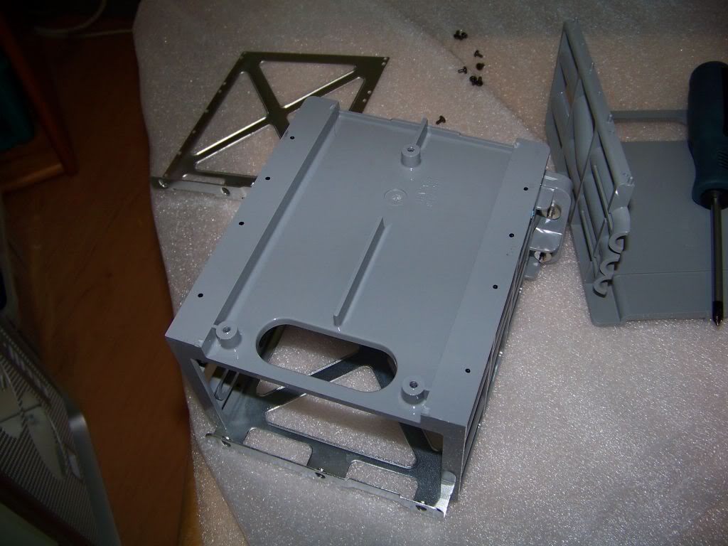
- At this point I grabbed some pliers and ripped off the card cage that was tacked to the back panel.
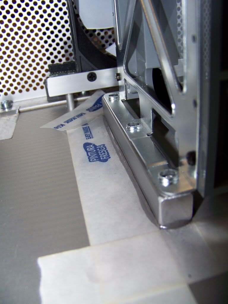
- I transferred the height of the “floor” of the tray to the back panel and now had the position of my MM back panel.
- I traced it out onto some tape that I had stuck onto the back.
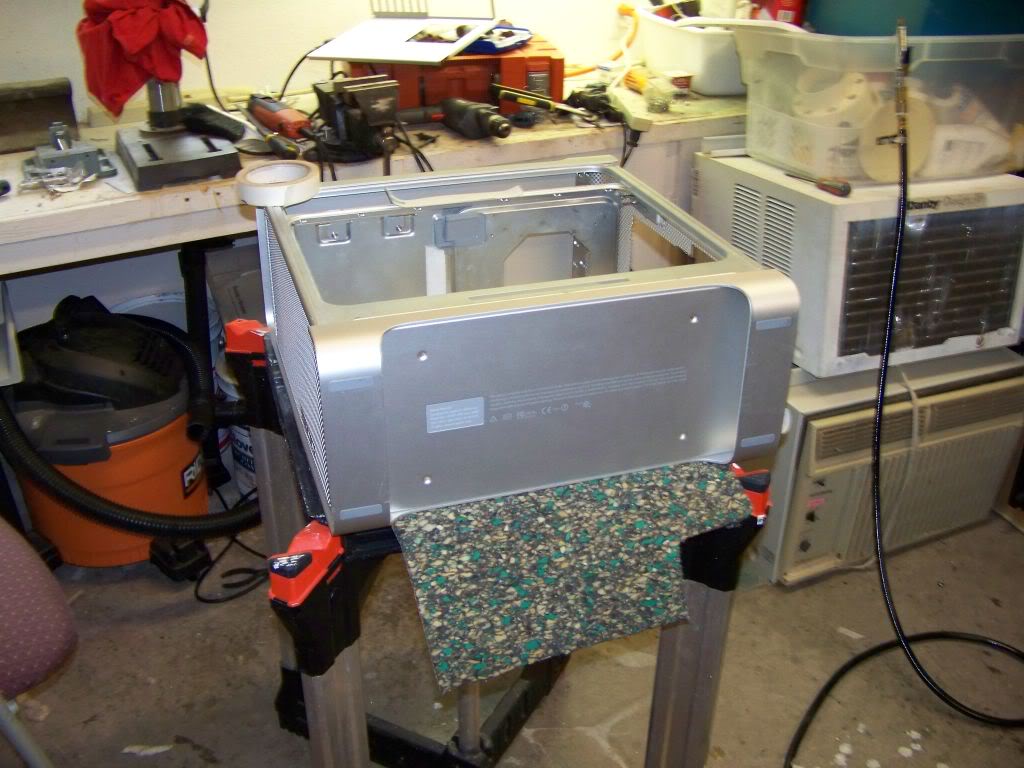
- I put on my safety goggles, grabbed my dremel, held my breath, and began to cut. I quickly discovered why the safety goggles are needed…. those cutting disks really fly apart when the break! OK, mental note, don’t put your body in the path of the cutting disk.
I then dry fitted things and marked where I needed to open some more space for MM back panel flanges and the 80mm fan bodies to sit nicely onto the back panel.
Once that was complete, I used my masking tape to help transfer the position of the standoffs to the MM tray and drilled holes so it could be mounted.
I also marked and cut out the part of the back panel that covered the case locking lever. Whew!
Last edited: