Contribute
Register

Mac Mini M1 Cube

I've connected the wires from the switch to the new connector this way:
  • 1 => 5V+ from AC/DC module
  • 3 => 5V- from AC/DC module
  • 4 => 1 on converter board
  • 5 => 6 on converter board
Not really sure if 3 is necessary
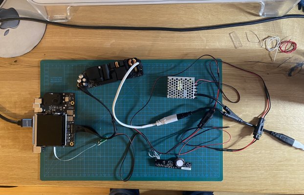
Thanks a ton, I have connected it like above (and it didn't work on the bench test (see picture below).

I also tried the same with a few changes:
  • 1 => 5V+ from AC/DC module
  • LED directly connected to 5V- with 470 Ohm resistor (steady glow)
  • 4 => 1 on converter board
  • 5 => 5 on converter board (I tested also 6 but it made no difference)
My LED obviously lights up, but the capacitive sensor is not turning on the board (shorting Pin 5 and 1 manually does). I assume you have tested it outside the cube as well - did it work without having everything grounded?
 

Attachments

  • IMG_2020.jpeg
    IMG_2020.jpeg
    2.5 MB · Views: 218
Last edited:
If I remember correctly, the sensor wasn’t working outside the cube. So I guess it should be grounded.
 
Thanks - couldn't get the sensor working, but everything else does. I went for a IO plate that is bolted into the cube so I can replace it when needed. Currently I am a bit handicapped as I am sick, but will post my pictures later.

Again - great work. The links to the required parts were really helpful and this project is wonderful. My favorite computer with blazing fast hardware ...
 
I am at the same situation as you are (I think). The switch works from time to time and on others it doesn't. The fix is to have the "program" line (wire 3) pulled to ground for a second or two, while power is supplied, then it works again.
I found this thread, which explains things somewhat:
https://www.tonymacx86.com/threads/cube-switch-modding.43924/
The downside is that I couldn't figure out an equivalent solution, yet. The person there soldered the pin of the LED (through a resistor) to the power_on line on an ATX motherboard, which is not what we have.

He also says:
Hooking up lines 1,4,5 ... (and making sure the metal plate on which the switch sits is grounded) make the switch work absolutely fine ... but not the LED.
I have done exactly this and my experience is different. This is not enough with our setup. Once the switch is in an non-working state, I have to ground line 3 and then it works again (sometimes I have to ground it twice).

I also want to find out what happens, if I ground line 3 all the time - but I guess it is the pulling down that matters, so the answer is likely no help.

Anyway, if you find a better solution, please let me know.
 
Last edited:
I wanted to share the results of the Mini Cube (with a small switch underneath to turn it on). The rest is a carbon copy of what @MacEnthousiast has created. I really enjoyed the build. Such a clean looking result.
 

Attachments

  • IMG_2032.jpeg
    IMG_2032.jpeg
    2.5 MB · Views: 300
Last edited:
Very nicely done @darkcruix ! At the moment, I also have the original Mac Mini switch hanging underneath to turn the it on. But I suspect my converterboard is broken, so I'm ordering another one to make sure. I'm also testing other capacitative switches to find one that works.
 
I’ve tried to get the original powerbutton working with a new converterboard. Even tried some other touch buttons, but with no luck. So, I decided to create a button in the bottomplate. I’ve used only components from the Mac Mini.

ABAB7741-1326-400C-8A78-D3973BAC581F.jpeg

2B2F3F65-AD29-4FF6-81A3-8DBCD0F82D7C.jpeg

3BF137B9-29BF-445D-B5A8-1F5C7775BE17.jpeg
 
Good job!
I don't understand English, through google translation software, sorry!
If the power adapter does not have DC 5V, then a DC-DC step-down module (12V to 5V) is required. The wiring is as shown in the figure. There is an important reminder that if the motherboard and the touch switch are not installed in the chassis, then the installation of the touch switch The screw holes need to be connected to the mounting screw holes of the motherboard, otherwise there will be constant restarts and shutdowns.

CUBE.jpg
 
Hi all, did you find a way to solve to wifi and bluetooth issues? Can you share a Link to the antenna used or point me to which one should work with an M1 Mini Board please?
 
@MacEnthousiast

Great job and thanks for the great guide. I also built an M1 into a G4 Cube, the Cube's on/off button also works so far, but the LED stays completely off.

I wired the on/off switch wires according to your instructions:

1 => 5V+ from AC/DC module
3 => 5V- from AC/DC module
4 => 1
5 => 6

The board of the switch is also grounded with the screw. As I said, on / off & holding down work perfectly. Only the LED remains dark.

In this video you can see that the LED turns on as soon as the Mac mini turns on, unfortunately I don't quite understand the wiring.....


An alternative would be to continue using the existing status LED of the Mac Mini or to clamp the LED of the G4 to this cable...
IMG_0512.jpg
 
Back
Top