Contribute
Register

Kiwi's Next Project - iMac G5

Status
Not open for further replies.
Question: would it be better if connectire was rotated 180 degrees so locking/key part of the connector was towards the inner part of the board. ?

Hi Kiwi

The best solution in my eyes is: interchange fan 1 and 2 connectors. Then mount J5 vertically, just like on the original logic board. The area below the Arduino USB connector can easily be used for low profile components such as resistors, diodes, driver transistors etc. (max. thickness about 8mm).
 
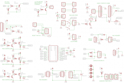
Here are my current schematic
SMCControllerPCB9.png

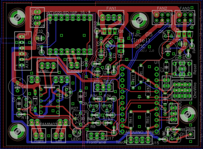
and PCB layout
SMCControllerPCB8.png
 
Hi MacTester

I have been doing some work on controlling fans via RPM value on my actual iMac machine (prototype SMC), with feedback from fan Tachometer (using interrupt pin). Below is a code fragment showing how it works. Note that my prototype SMC has a single LM317 (voltage output) controlled by PWM, the final version will have PWM outfit for each fan.

I deal with this by taking an average of the two fan's RPM, as feedback to a single PWM output. This of course will be upgraded with the new SMC

In summary a Fan Controller

  • getFanRPM() - sets up the interrupts (initially) and computes the Fan RPM value, this is used by the fan controller to read the current value.
  • setFanControlTarget() - Set up the fan controller (background task), and sets the desired RPM
  • readInputSetFanPWM() - Is the background controller, it reads the Current RPM compares it to the target and adjusts the PWM output PIN setting it to a desired value.
  • compareCurrentAndTarget() - Defines the amount to adjust the PWM by (up or down), by comparing current to the target PWM, and has built in logic to smooth out transitions. Unfortunately the LM317 is not a linear relationship between PWM and Output RPM, This method doesn't really account for this. This logic will probably be improved with new BJT PWM controller.


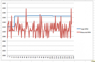
I have also attached a graph showing the measured RPM's, on each call to readInputSetFanPWM(), to see the comparative accuracy of this reading, on the whole it is pretty good.

Note The following code compiles, but is not tested, The full (tested) sketch can be found on GitHub.

AND also has been tested with the Display sleep logic also running via the Brightness Menu

Code:
#include <PWMFrequency.h>
#include <SimpleTimer.h>

// NUMBER OF FAN NPUTS
#define FAN_COUNT 2

// The Pins For Fan Input
const byte FAN_RPM_PIN[] = { 0, 1 }; 

// Interrupts that fans are attached to.
#define FAN1_INTERRUPT 2 
#define FAN2_INTERRUPT 3 

// Time between controlling the Fans
#define FAN_CONTROL_PERIOD 5000

// Number of Output Fan Control PWM's
#define FAN_CONTROL_COUNT 1

// PWM Fan Speed Voltage OUTPUT
const byte FAN_CONTROL_PWM[] = { 9 } ;

// Prescale Values for controlling PWM
const int FAN_CONTROL_PWM_PRESCALE[] = {1};

// Values in RPM
#define OFF_FAN_VALUE 100
#define MIN_FAN_VALUE 1200
#define MAX_FAN_VALUE 5000


// A general purpose timer, and some misc constants
SimpleTimer timer = SimpleTimer();

// 
// ========================================
// MAIN ARDUINO SETUP (1x during startup)
// ========================================
//

void setup () {

  setFanContolTarget(2100); // Set the RPM Value
}

// 
// ========================================
// MAIN ARDUINO LOOP (Called Repeatidly)
// ========================================
//

void loop () {

  timer.run();
}

//
// ----------
// RPM INPUTS
// ----------
//

volatile long fanRotationCount[FAN_COUNT];
unsigned long fanTimeStart[FAN_COUNT];

void interruptFan1() {
  fanRotationCount[0]++;
}

void interruptFan2() {
  fanRotationCount[1] ++;
}

void interruptFan3() {
  fanRotationCount[2] ++;
}

int getFanRPM( byte fan ) {
  
  static boolean started = false;
  if (!started) {
    started = true;
    
    for ( byte fan=0; fan<FAN_COUNT; fan++ ) {
      // Start Up the RPM by setting PIN 
      pinMode(FAN_RPM_PIN[fan],INPUT_PULLUP);    
    }
    
    //and attaching interrupt
#ifdef FAN1_INTERRUPT
    attachInterrupt(FAN1_INTERRUPT,interruptFan1,FALLING);
#endif
#ifdef FAN2_INTERRUPT
    attachInterrupt(FAN2_INTERRUPT,interruptFan2,FALLING);
#endif
#ifdef FAN3_INTERRUPT
    attachInterrupt(FAN3_INTERRUPT,interruptFan3,FALLING);
#endif
  }

  // pulses counted; /2 pulses per rotation; *60000 milliseconds per minute; /millis elapsed
  double ret = fanRotationCount[fan] /2L *60000L / ( millis() - fanTimeStart[fan] );
  fanRotationCount[fan] = 0;
  fanTimeStart[fan] = millis();
  return ret;
}

//
// --------------------------
// Fan Output Control
// --------------------------
//

// The output Fan RPM (or mVolts for LM317) we desire
int targetFanValue = MIN_FAN_VALUE; 

// Set the Target Fan RPM ( cVolt LM317) for a specified Fan
// this can be used for independant Fan Control.
// Legacy Mode only support a singe (0) target
void setFanContolTarget(int value) {
  
  // set the target voltage  
  targetFanValue = value;
  
  // init the controller
  initFanController();
}

boolean debugFans = true;
int fanControlTimer = -1; // timer that controls fan voltages

void initFanController() {
  
  if (fanControlTimer>=0) return;

  // set up the three PWM outputs
  for ( byte fan=0; fan<FAN_CONTROL_COUNT; fan++ ) {
    
    digitalWrite(FAN_CONTROL_PWM[fan],HIGH); // ensures minimum voltage
    pinMode(FAN_CONTROL_PWM[fan],OUTPUT);   // PWM Output Pin For Fan
    setPWMPrescaler(FAN_CONTROL_PWM[fan],FAN_CONTROL_PWM_PRESCALE[fan]); // Sets 31.25KHz / 256 = 122Hz Frequency
  }
  
  // setup a timer that runs every 50 ms - To Set Fan Speed
  fanControlTimer = timer.setInterval(FAN_CONTROL_PERIOD,readInputSetFanPWM);
}

// Just Default Mid Range PWM Values
byte currentPWM[] = { 30, 30, 30 }; 

byte getCurrentPWM(byte fan) {
  return currentPWM[fan];
}

void readInputSetFanPWM() {

  // Average to the Two Fans RPMS Speeds
  int currentFanValue = ( getFanRPM(0) + getFanRPM(1) ) / 2;

  //byte factor = 1;
  byte factor = compareCurrentAndTarget(currentFanValue,targetFanValue);
  
  if ( currentFanValue > targetFanValue ) {
    
    // Slow fans down slowely, rather than hard off.
    // increasing PWM duty, lowers the voltage
    currentPWM[0] = currentPWM[0]<=(255-factor) ? currentPWM[0]+factor : 255;
    
  } else if ( currentFanValue < targetFanValue ) {
    
    // Slowly ramp up the fan speed, rather than hard on.
    // decreasing PWM duty, increases the voltage
    currentPWM[0] = currentPWM[0]>=factor ? currentPWM[0]-factor : 0;
  }

  if ( debugFans ) {  
    Serial.print(factor);
    Serial.print(F("\t"));
    Serial.print(targetFanValue);
    Serial.print(F("\t"));
    Serial.print(currentFanValue);
    Serial.print(F("\t"));
    Serial.print(currentPWM[0]); // Current PWM
    Serial.println(); 
  }
  
  // write the PWM  
  analogWrite(FAN_CONTROL_PWM[0],currentPWM[0]);
}

// <5% - then 0
// <10% - then just inc / dec by 1
// <20% - 3
// <50% - 5
// >50% - 10
byte compareCurrentAndTarget(int current, int target) {
  
  int diff = current-target;
  if (diff < 0) diff = diff * -1;
  byte percent = 100.0f* (float)diff / (float)target;
  
  if (percent<5) {
    return 0;
  } else if (percent <20) {
    return 1;
  } else if (percent <30) {
    return 2;
  } else if (percent <40) {
    return 3;
  } else if (percent <50) {
    return 4;
  }
  return 5;
}

Screenshot_20_02_2015_9_56_am.png
 
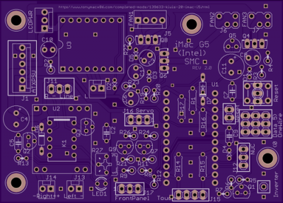
And here is a rendering courtesy of OSH park

Nice! Have you ordered your boards?

I have been doing some work on controlling fans via RPM value on my actual iMac machine (prototype SMC), with feedback from fan Tachometer (using interrupt pin). Below is a code fragment showing how it works. Note that my prototype SMC has a single LM317 (voltage output) controlled by PWM, the final version will have PWM outfit for each fan.

Thanks kiwi. Looks like I can order my boards now. I was very busy with my board layout this week and did not spend any time with the software part.

MacTester
 
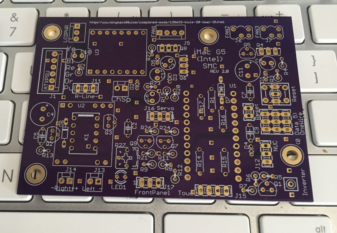
My SMC boards from OSH Park arrived today! ;)

IMG_3534.jpg


However my Guest room which doubles as my computer room is occupied for the next few weeks so won't really be able to progress at this stage.

Kiwi
 
My SMC boards from OSH Park arrived today!

Looks good. The distance from the US to Australia and to Switzerland seems to be identical. ;)

Hope you will find some time to work on your SMC.

MacTester
 
So I populated most of the discrete components on the board. Just missing the main components, the fan transistors, and capacitors, and the chime to amplifier coupling capacitor. These are on order, and I now have the process of testing this out, and mounting the major components.

Kiwi

IMG_3537.jpg
 
Hi Kiwi

Good to see, that you make some progress too. Looks very good! :thumbup:

I've just implemented the interrupt fan rotation detection (uses RPM now) in my sketch. I could now mount the SMC into my G5 build, but I want to solve the "serial command missed issue" first.

MacTester
 
Hi Kiwi

Good to see, that you make some progress too. Looks very good! :thumbup:

I've just implemented the interrupt fan rotation detection (uses RPM now) in my sketch. I could now mount the SMC into my G5 build, but I want to solve the "serial command missed issue" first.

MacTester
My iMac is in the Guest room, so can't spend time on it until next week. The answer is to get the Arduino, to send a "OK" message confirmation when it gets the BA, BD commands, this should be trivial on the Arduino Side. On the Mac side we just need to implement something like this.

Basically it waits (short time) to receive a response, and if it doesn't get the OK then it retries, until it does get a response.

Of course this is untested, which thinking about it may be difficult if the inverter is being deactivated. it may be easier to test in a more general purpose method, but once tested this could be applied to any message sent.

The current code is on GitHub

Code:
(void) activate_inverter {
	
    //
    // Activate Inverter on Arduino
    //
    
    Boolean confirmed = false;
    
    while(! confirmed) {
    
        // make sure serial port open
        if (serialHandle<=0) serialHandle= serialport_init([serialPort UTF8String], serialBaud);
        
        // The command we send the the Serial port "B" Brihgtness "R" Read
        char buf[32] = {"BA\n"};
        serialport_write(serialHandle, buf);
        
        // read result from serial port, until receive \r
        serialport_read_until(serialHandle, buf, '\n', 32, 500);
    
        // TODO -> Then Check for a Message "OK"
        if ( buf[0]=='O' && buf[1]=='K' ) {
            // IF received OK, then dont resend
            confirmed = true;
        }
    }
    
    NSLog( @"Inverter Activated");
}
 
Status
Not open for further replies.
Back
Top