Contribute
Register

Kiwi's Next Project - iMac G5

Status
Not open for further replies.
Part 4 - Inverter

I did some work last night, and measured voltages on the inverter. The following diagram shows the pinout on the motherboard connector. It is one of those very small connectors similar to a cube power sensor.
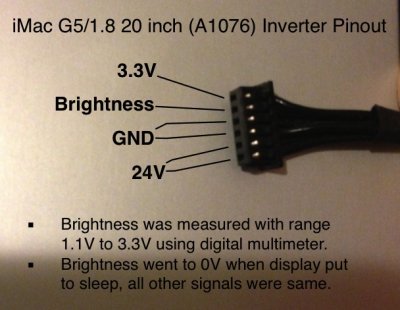
iMac G5 Inverter.jpg

The cable is not colour coded, and has one less wire than a G4. Brightness seems to runs off 3.3v, and I assume can be controlled via PWM. When I let the display go to sleep this pin went to 0V, and the backlight was turned off. When I actually put the computer to sleep ALL inverter voltages went to 0V.

I can use the above In my micro controller firmware to achieve a virtual display sleep, by setting the PWM duty cycle to 0, rather than shutting down the inverter fully.

Also confirmed voltages on PSU are as per this layout.
http://jimwarholic.com/2010/03/measuring-imac-g5-power-supply-voltages-at-connector-plug-pinouts.php

Also measured voltages on Fans, they of course run off 12V. I also discovered the computer actually has a third "intake" fan at the bottom near the CPU.
 
Hi Kiwi, so comparatively speaking then...

The G5 3.3V is the G4 Orange
The G5 Brightness is the G4 Green
The G5 24V is the G4 Blue
The G5 GND is the G4 Black

The 24V you have shown uses 2 wires. Are those 12V each with matching GND wires?

The G4 5V red wire (that MacTester and I have connected to VEDID pin 14) doesn't seem to have a place in the G5, nor the G4 purple wire, of which the use hasn't been nailed down yet.

Interesting to note the differences that Apple built in only one generation later...


Ersterhernd
 
Hi Kiwi, so comparatively speaking then...

The G5 3.3V is the G4 Orange
The G5 Brightness is the G4 Green
The G5 24V is the G4 Blue
The G5 GND is the G4 Black

The 24V you have shown uses 2 wires. Are those 12V each with matching GND wires?
No it is 24V provided to both pins. Remember the main PSU has a 24V pin on the connector. I have also tested the resistance across matching pins (while disconnected), and they show 0 ohms, so assume two wires are used to ensure enough current can be delivered.

The G4 5V red wire (that MacTester and I have connected to VEDID pin 14) doesn't seem to have a place in the G5, nor the G4 purple wire, of which the use hasn't been nailed down yet.

Interesting to note the differences that Apple built in only one generation later...

Ersterhernd
Agree with your statement. The G5 is much simpler, I just have to supply 3.3V and 24V and wire up the PWM brightness, and thats it.

one generation... :) The G4 to G5 was a fairly big generational gap in many respects...
 
Kiwi,

Your layout plan and the logic diagram look good. Reusing the old PSU will work, but as you said it's old and could break.

I think, that should be no problem, if the Picaxe wiring is done in accordance with the manual. You should do a test on a breadboard, before you disassemble the iMac and test the desired functionality. The Picaxe micro controllers have limited multitasking abilities (depending on the chip type), if the PWM functionality is used.

Picaxe microcontrollers appear to be the new standard in iMac mods. ;) :thumbup:

Can't wait to see your progress

MacTester
Part 5 - Architecture Revised

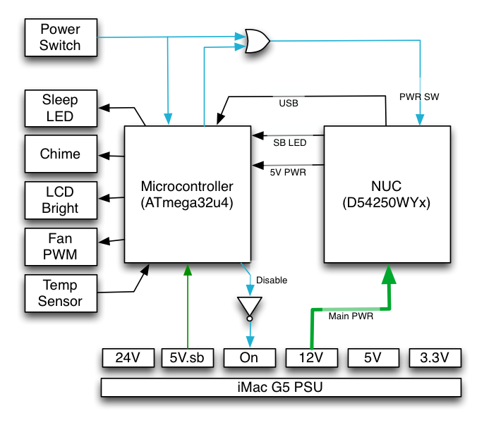
I finalised the architecture, and made the power management fail safe. i.e. A failure of the micro controller should leave the computer fully operational. The change is the addition of a NOT gate - so the m.c. actively puts the PSU to sleep. And an OR gate so the users power switch can trigger the NUC independently to the m.c.

iMac%20G5%20Architecture.png


The NOT GATE actively puts the PSU to sleep. And an OR gate so the users power switch can trigger the NUC independently to the m.c.

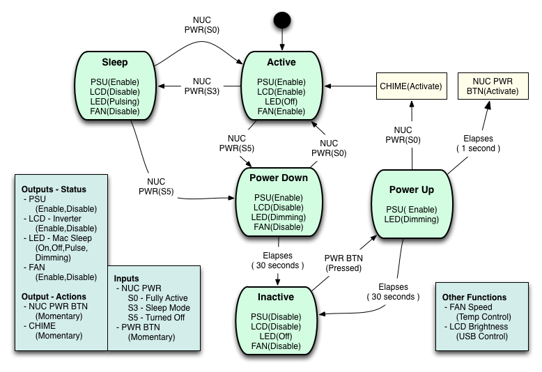
The next diagram, a "State" diagram shows how the m.c. will manage the various modes or "states" of the Mac. A state is shown as a Green box and shows what outputs will be set at each state that are appropriate for the state. The arrows between states show the conditions (or inputs) that will be needed to move from one state to another. The yellow boxes show actions that happen during a transition from one state to another.

iMac%20G5%20Power%20States.png


Here is a description of each State:

ACTIVE : This is the default state when the m.c. starts up. Making this the default allows us to "flash" the firmware from the completed computer itself, while leaving the computer fully operational. If we just plugged the machine into power we would probably go to "Power Down" state very quickly.

The S number's. S0 S3 S5, are the input conditions read from the NUC so we can detect its state. These are read from USB power and front panel LED.

SLEEP : Should be obvious, when we transition to this state we just disable the Inverter, Fans, etc. We can go from here back to Active, or to Power Down if the Nuc is powered off.

POWER DOWN : This is a state we reach when we detect that the Nuc is powered off. From here we can go back to Active if Nuc is powered on, OR if we stay in this state for 30 seconds (controlled via timer) we then go to the "Inactive" state.

INACTIVE : This is the state where we get the m.c to shut everything down (including the main PSU), from this point there is really only one escape, the user presses the power button. When this happens we can go to "Power Up" state

POWER UP: Basically we enable the main PSU so the NUC has main power, but of course the user button press wouldn't have got to the NUC as it was powered down at the time So after enabling the PSU we wait about a second, then send another Power button press to the NUC.

Note:
  • If the NUC powers on then we go to "Active", at the same time triggering the startup chime.
  • If the NUC doesnt come on in 30 seconds (unsure why), then we can power back down to the "Inactive" state
Additionally

The m.c. will also control Fan speed from temperature inputs, and control LCD Inverter brightness via USB (serial port) via software, that I hope to write on the Mac. This software will just be a utility to set brightness, but could also use it to control FAN speeds, and temperature thresholds. Would like to store these sorts of parameters in EEPROM on m.c. so it survives reboot.

I am working on the firmware design as none of the parts I have been ordering have arrived so far. And of course still no NUC available for local order. But can prototype all the above without a NUC.

Any thoughts. Questions. Comments.

Kiwi
 
Hi Kiwi, I just completed the pulsing LED install in my first NUCiMac, the 2nd one is already done. Theres a couple of interesting discoveries I made that you should know about the NUC. The Haswell version may be different, but the i3 DC3217IYE shows the following results...

1. Pin 9 of the FPH only outputs 5V when the NUC is on, and Pin 4 is empty.
2. Pin 9 outputs 5VSB in the powered off state when pin 9 and 4 are connected.
3. Connecting both pin 2 & 4 to power and ground the LED circuit kept pin 9 active when powered off.
4. Connecting pin 2 to power the LED circuit while using a Ground on the PicoPSU kept pin 9 off when the NUC was powered down, but the LED stayed on when the power was off. I had the BIOS set to leave the LED ON during S3.

It seems a little strange that pin 9 actually moves to a 5VSB when the ground pin 4 is connected. Perhaps this is to accomodate an infrared remote startup of the NUC, who knows. Regardless, the NUC may react a little differently than you have planned, it certainly did for me.

Your layout looks excellent.


Ersterhernd
 
Any thoughts. Questions. Comments.

Just wow. Your concept looks very professional! :thumbup:

The Haswell version may be different, but the i3 DC3217IYE shows the following results...

...It seems a little strange that pin 9 actually moves to a 5VSB when the ground pin 4 is connected. Perhaps this is to accomodate an infrared remote startup of the NUC, who knows. Regardless, the NUC may react a little differently than you have planned, it certainly did for me.

Be careful! Pin 4 is not GND, it switches the LED on (if pulled to GND) and off (if pulled to 5V) ->

The CS header on my DC53427HYE NUC has the following logic.
Power LED: (BIOS Setting = "on" during sleep)
-Pin 2 has always 5V,
-Pin 4 is pulled to GND if LED is on (NPN logic)

Pin 9:
-5V if NUC is on
-0V if off or during sleep

MacTester
 
Thx MacTester, I never tried pin 4 other than connected in an LED circuit controlled by the Picaxe. The sleep pulse worked great, but the picopsu wouldn't shut off when the NUC was powered down because pin 9 was still live, thus the backlights and fan stayed on. During sleep, the pico was off. This was surprising to me.


Cheers!
 
Just wow. Your concept looks very professional!

Be careful! Pin 4 is not GND, it switches the LED on (if pulled to GND) and off (if pulled to 5V) ->

The CS header on my DC53427HYE NUC has the following logic.
Power LED: (BIOS Setting = "on" during sleep)
-Pin 2 has always 5V,
-Pin 4 is pulled to GND if LED is on (NPN logic)

Pin 9:
-5V if NUC is on
-0V if off or during sleep

MacTester

Sleep Detection

I had read your posts before on this subject, without a NUC to experiment with nothing can be confirmed. However my idea was to use the Dual Colour power LED output to detect sleep, as per the following circuit:

The transistors isolate, and detect voltage differential both
- from Pin 2 -> 4 via Q1 indicates the S0 State AND
- from Pin 4 -> 2 via Q3 indicates the S3 State

EDIT: The bolow circuit was simplified, the final design just direclty connected the signals to input pins on the microcontroller

1024x768


PSU Control

The following circuit to control the PSU is:

Putting 5V on the input turns the transistor off and disable the PSU

540x405


NUC Power Switch Control

The following circuit to control the NUC Power Switch Pin 6 or 8 to ground is:

Basically it is an OR function, where either input can ground the output.

EDIT: The following circuit was utimately replaced with http://www.tonymacx86.com/imac-mods/107859-kiwis-next-project-imac-g5-13.html#post776138

540x405


Thx MacTester, I never tried pin 4 other than connected in an LED circuit controlled by the Picaxe. The sleep pulse worked great, but the picopsu wouldn't shut off when the NUC was powered down because pin 9 was still live, thus the backlights and fan stayed on. During sleep, the pico was off. This was surprising to me.
Its really hard to know what your issue is, but agree with Mactester, be carful that you don't treat pin 4 as a ground, it could be going positive in standby mode. This is my guess.

Kiwi
 
Still waiting for a NUC to be available for purchase, so killing some more time in design. Here is a complete diagram for the component layout and interconnect wiring.

Kiwi

iMac%20G5%20Wireing.png
 
The CS header on my DC53427HYE NUC has the following logic.
Power LED: (BIOS Setting = "on" during sleep)
-Pin 2 has always 5V,


MacTester

Even when the NUC is off? Like a 5VSB?
 
Status
Not open for further replies.
Back
Top