#include <SimpleTimer.h>

// A general purpose timer, and some misc constants
SimpleTimer timer = SimpleTimer();

// Other Variables
float currentPWM = 150; // Roughly equal to 3.3v
float targetVOLT = 3.3; // current target voltage to match

// Pin Assignments
const int FAN_CONTROL_POUT = 5;
const int FAN_OUTPUT_V = 1;

void setup () {

  // setup pin outp
  pinMode(FAN_CONTROL_POUT,OUTPUT);

  // a timer that simulates reading a temp, and setting Voltage
  timer.setInterval(1000,voltageController);

  // setup a timer that runs every 20 ms - For Fan Speed
  timer.setInterval(20,fanCallback);
}

void loop () {

  // Let the timer run backgound tasks
  timer.run();
}

void voltageController() {

  // Simulates setting the voltage to a value
  // latter this will be based on reading a temperature
  targetVOLT = targetVOLT + 0.1;
  if (targetVOLT>10.0) targetVOLT=3.3;
}

void fanCallback( ) {

  // read the current output voltage
  float currentVolt = readVoltage(FAN_OUTPUT_V) * 2.0;

  // compare it to target, and set new PWM
  if ( targetVOLT < currentVolt ) {
    currentPWM = currentPWM + 1;
  } else if ( targetVOLT > currentVolt ) {
    currentPWM = currentPWM - 1;
  }

  // write the PWM to the output port.
  analogWrite(FAN_CONTROL_POUT,currentPWM);
}

float readVoltage( int sensorPin ) {

 //get voltage reading from the input
 int reading = analogRead(sensorPin);

 // converting that reading to voltage, for 3.3v arduino use 3.3
 return ( 5.0 * reading ) / 1023.0;
}

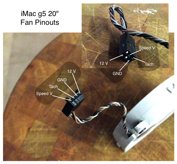
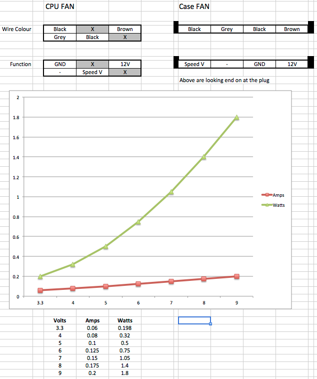
")