Contribute
Register

Info on G5 Fans

Status
Not open for further replies.
Joined
Aug 28, 2012
Messages
31
Motherboard
Abacus
CPU
Mouse in a wheel
Graphics
Crayons
Mac
  1. 0
Classic Mac
  1. 0
Mobile Phone
  1. 0
Hi All, this is my first post on the forum. I picked up a PowerMac G5 cheap from work which they were getting rid of. It looks SWEET and works perfectly but is pretty much useless to me as I mainly use Linux, and have only owned a mac for about 12 months, so I don't have a use for a "classic" mac. I decided to do a case mod on it. I'll document it on a different thread. I plan on reusing all the fans, and every piece of information I can find on the fans is incomplete, so I decided to share my findings.

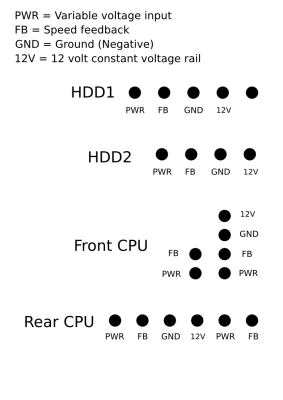
First of all, the commonly known stuff, pinouts. On my G5, the cables are all black so I'm taking a guess as to which one is pin 1:
PIN 1) - Variable voltage power supply (speed control input). This input varies from 3.9v RMS (5v Peak) at minimum speed to a smooth 12VDC at full speed.
PIN 2) - Speedo. This is an output from the fan back to the controller to feedback the fan speed. It is a 50% duty cycle 4.0v square wave which varies from 28Hz at minimum speed to 111Hz at full speed
PIN 3) - Ground (negative)
PIN 4) - 12V (for fan logic?) This appears to be a supply for the speedo feedback circuit and any other digital/control circuits on the fan. I believe they have this separate 12V rail because at the minimum speed the Variable voltage rail dips to about 1.2v.

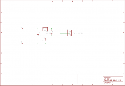
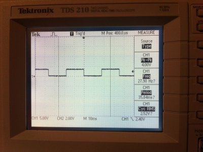
Now some reference pictures of the traces for the speed control and the speedo feedback. The two square wave traces are the feedback line (pin 2?), one at full speed, one at minimum speed, the saw-tooth shape trace is the power supply rail at minimum speed, and the flat 12v line is the power supply rail at full speed.
 

Attachments

  • FeedbackFullSpeed.jpg
    FeedbackFullSpeed.jpg
    1 MB · Views: 1,122
  • FeedbackMinimumSpeed.jpg
    FeedbackMinimumSpeed.jpg
    1 MB · Views: 1,266
  • PowerRailFullSpeed.jpg
    PowerRailFullSpeed.jpg
    1 MB · Views: 1,027
  • PowerRailMinimumSpeed.jpg
    PowerRailMinimumSpeed.jpg
    1 MB · Views: 1,019
I can not speak for the community. I do not reuse the G5 fans because of the noise that they generate when run on a fixed DC value. The alternative is to use today's fans that are cheap, low power and quiet; well some are not cheap.

neil
 
I agree with neilheart. I tried to use those fans at my build but they were tooooo loud even if I supply them the lowest voltage they could start spinning (about 5-7 VDC). So I end up buying some low noise and low spin fans and I replaced the original ones.
 
Yes, it is true we have all replaced our original fans with quiet replacements.

I find it interesting however. I guess these waveforms were taken from a running G5 to see what was being delivered? If so, I wonder if the native use of G5 fans being fed with a square wave signal (say 5 volts rms) results in a quieter use of the the fans than straight undervolting down to 5volts and if so, how much quieter are they?

Having just got a genuine G5 2.7GHz dual up and running in good order I must say that I do not find the sound that it makes to be as intrusive as I thought it would be. Its really quiet (!). Maybe if the fans could be powered on a hack in a way closer to the way the G5 runs them natively then more people would decide to use them.
 
I ended up buying Noctua fans instead of reusing these fans.

Sidenote: Those Delphi fans can also take more than 12V without damage. If you ever had a PowerMac that had a failed LCS (then went into KP), those fans will rev up to maximum speed and you can hear them across the next room. It's that LOUD! I don't mean loud like "not quiet", I mean LOUD as loud as a big shop vacuum. I tried to recreate the sound level with those Delphi fans, and I had to feed it +24V and more to recreate that sound I heard.

I agree with others, without the proper fan control, these fans will be loud even when run undervoltage. And even the best effort undervoltage doesn't deliver... it's still loud. (Plus, you also just can't *initially* feed these Delphi fans a smaller voltage (to keep quiet), because it wouldn't spin. You need to give it a boost (feed it 12V), then ramp down the voltage low enough to keep it spinning.) If you have a G5, you'd know what I mean when you first turn on the computer... the fans rev up for about a sec, then slow and quiet down.
 
Thanks for the response. Well, the answer to your fan noise is simple, the apple fans are not the same as your average pc fan. There is a 12v supply and a speed control input, as well as a speed feedback.

If you connect the 12v rail to 12v, the fan will reliably start spinning when the speed control input is at about 2.5v (not the 5-7v claimed below). The fans reach full speed when the speed control input is raised to 12v. The reason you are all having so much trouble reliably starting the fans at the lower voltage is that you are also dropping the voltage on the 12v supply pin. (am I right?:p)

To use the apple fans you need a simple speed controller. This can easily be made using an LM317 regulator and a potentiometer. I am tired now, but I will post a speed control circuit later.

Goodnight.
 
As promised, attached is a schematic for a speed controller for the G5 fans. The output (on the right) has pinouts to match the HDD fan that I posted pinouts from in my initial post, but with a change of connector should work for all g5 fans. I have successfully used the method, but not the circuit to control the G5 fans. If someone wants to try the circuit, I would be happy to provide advice. I will be trying it myself, but I take a long time to get around to projects with work and such getting in the way.
 

Attachments

  • circuit.png
    circuit.png
    12.6 KB · Views: 4,589
And for reference, attached is the pinouts for he G5 fan connectors.
 

Attachments

  • G5_fans.png
    G5_fans.png
    59.6 KB · Views: 11,297
Hi Sheriff,

Interesting stuff.

Doesn't the circuit you give simply provide a variable but DC voltage rather than the pulsed voltage that you show in the first post? If so, then presumably as long as 12v constant is provided to the correct input then I assume that a normal dc fan controller can be used to give the variable signal.


Thank you for having posted your findings and looking forward to any future posts.
 
Status
Not open for further replies.
Back
Top