
- Joined
- May 27, 2020
- Messages
- 19
- Motherboard
- ASRock B550M
- CPU
- Ryzen 3600X
- Graphics
- RTX 2070 Super
- Mac
- Mobile Phone
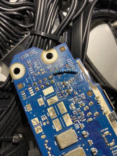
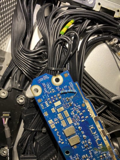
Here are some pics of the board.
Looks like the resistors combined are around 300 ohms.
The last part of the original jack sensing stuff was some smd resistor. That was roasted in two with the soldering iron, so that the bridge is the only path to the jack plug.
In short: the resistors go directly from the 8pin to the last part of the board before the jack plug.
I hope this helps more people to make this work!
Now that I have looked at the other threads with the wiring again, I see that these resistors are for the power LED.
The jack sensing stuff was done in a similar way, but with a resistor in the wiring harness.
Looks like the resistors combined are around 300 ohms.
In short: the resistors go directly from the 8pin to the last part of the board before the jack plug.
I hope this helps more people to make this work!
Now that I have looked at the other threads with the wiring again, I see that these resistors are for the power LED.
The jack sensing stuff was done in a similar way, but with a resistor in the wiring harness.
Attachments
Last edited:
")