BoomR
Moderator
- Joined
- Dec 18, 2011
- Messages
- 1,256
- Motherboard
- Gigabyte Z490 VISION D
- CPU
- i9-10850K
- Graphics
- RX 580
- Mac
- Classic Mac
- Mobile Phone
Stumbled across the great builds by sleppek and eelhead (and later a couple more great threads)...and I was bit by the fever bug!
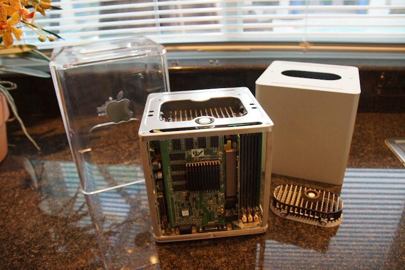
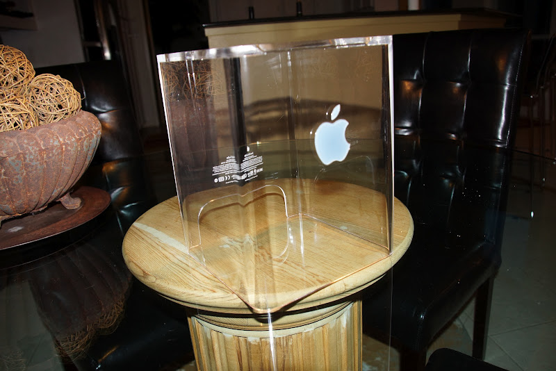
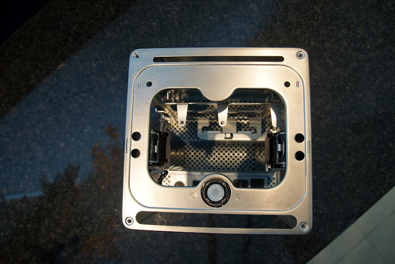
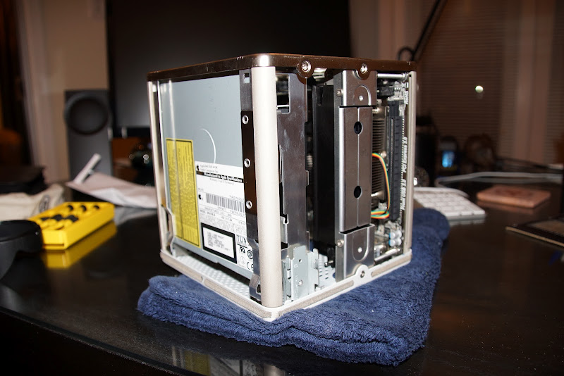
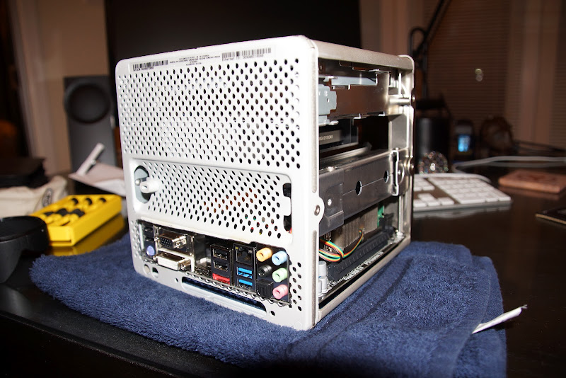
SOOoo... found this G4 Cube on eBay in the local DFW area and began the deconstruction:
Began gathering my build components:
ASRock H77M-ITX LGA 1155 (Intel H77 HDMI SATA 6Gb/s USB 3.0) Mini ITX Intel Motherboard
http://www.newegg.com/Product/Product.aspx?Item=N82E16813157311
Intel Core i5-2500K Sandy Bridge 3.3GHz Quad-Core Desktop Processor Intel HD Graphics 3000
http://www.newegg.com/Product/Product.aspx?Item=N82E16819115072
Crucial Ballistix sport 8GB 240-Pin DDR3 SDRAM DDR3 1600 (PC3 12800) Desktop Memory
http://www.newegg.com/Product/Product.aspx?Item=N82E16820148540
Corsair Force Series 3 CSSD-F120GB3A-BK 2.5" 120GB SATA III Internal Solid State Drive
http://www.newegg.com/Product/Product.aspx?Item=N82E16820233206
Updated: Sony Optiarc Slim Slot-loading Combo Blu-ray Combo Drive Model BC-5650H-01
http://www.newegg.com/Product/Product.aspx?Item=N82E16827118070
GELID Solutions Slim Silence i-Plus (CC-SSilence-iplus) 75mm Ball Bearing CPU Cooler
http://www.newegg.com/Product/Product.aspx?Item=N82E16835426028
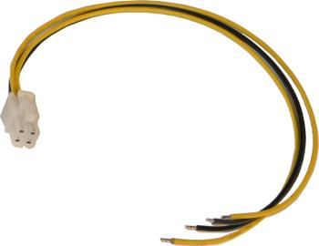
Mini-Box PW-200-M, 200w output, 12v input DC-DC Pico Power Supply, with optional P4-ATX Cable
http://www.mini-box.com/PW-200M-DC-DC-power-supply
Mini-Box Model: STD-12160 AC-DC 12V / 16A Switching Power Adapter (100/240V)
http://www.mini-box.com/12v-16A-AC-DC-Power-Adapter
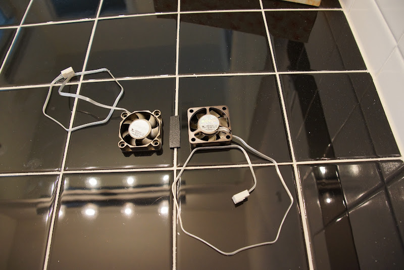
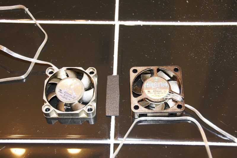
SilenX IXP-11-14 40mm Case Fan (2)
http://www.newegg.com/Product/Product.aspx?Item=N82E16835191001
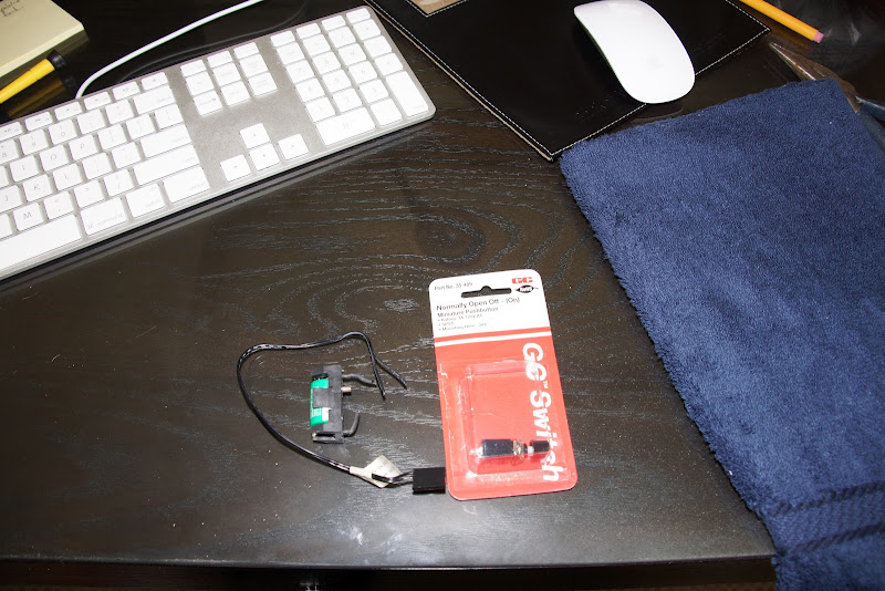
EDIT: Added Sabrent Mini Bluetooth USB 2.0 Wireless Adapter - model BT-USBT
http://www.frys.com/product/6103319
Already owned:
Apple Wired Keyboard
Apple Wired Mouse
Background on my motherboard choice...
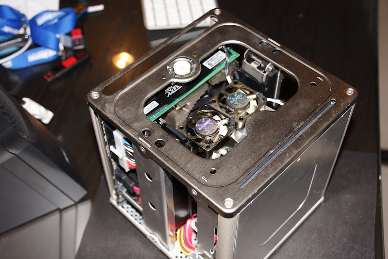
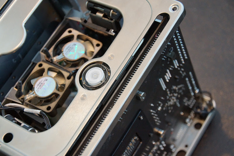
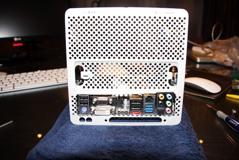
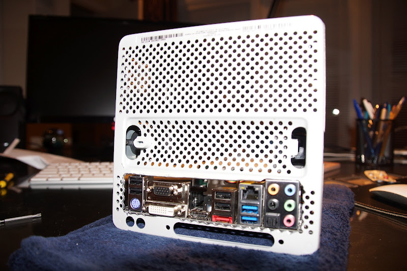
The reason I went with the ASRock board is because I wanted to try & orient the motherboard close to the original position & eventually try getting the touch-sensor power switch/power LED functional.
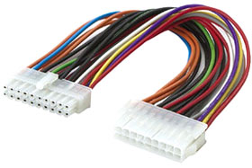
Most every other board I found (like Gigabyte) had the DIMM slot almost flush with the edge of the circuit board. I was trying to minimize interference issues. A few other ASUS and ASRock boards that had a bit more space between edge of board & DIMM also had the ATX connector just a bit too close & taking up some of the space I felt I needed.
My BIGGEST challenge to date is that there is no current DSDT file in the TonyMacx86 database. Worse yet, there is no patch (yet) in Maldon's site either. So it's been pretty painful getting a fine-tune build.
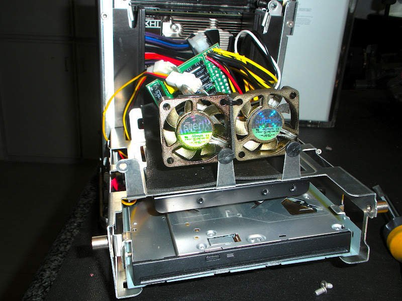
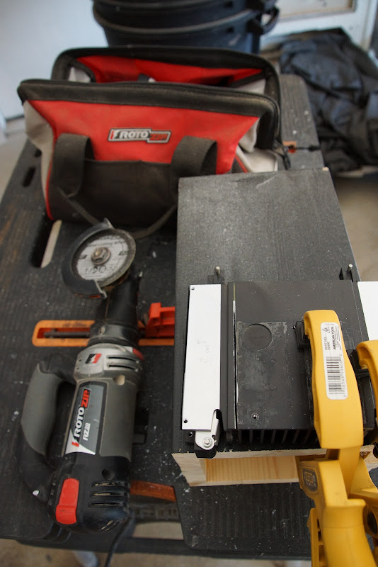
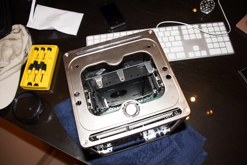
...and now, on with the show! Just for yucks, here's a shot of the G4 guts completely disassembled:
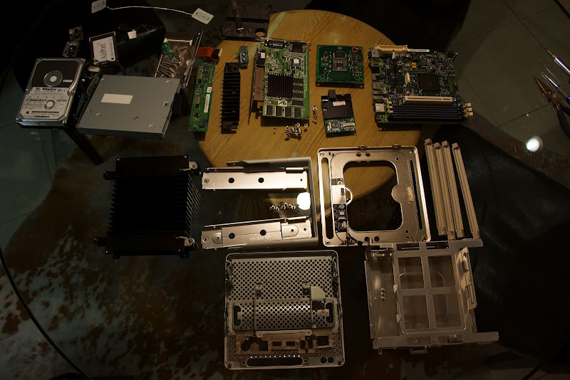
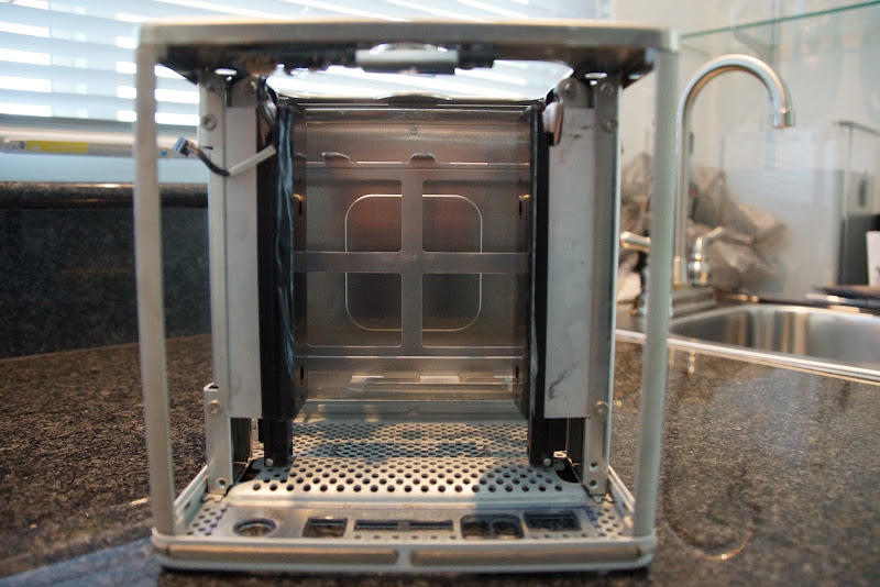
98% of the stuff at the top half of the pic is unusable. The stuff at the bottom are the key components of the "cage" that will hold all the updated components.
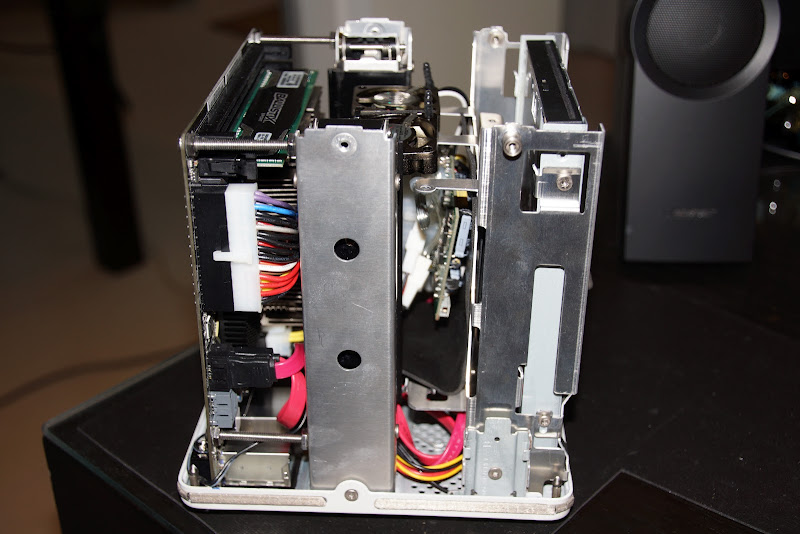
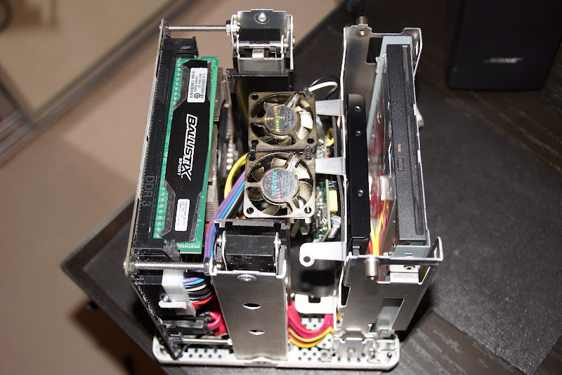
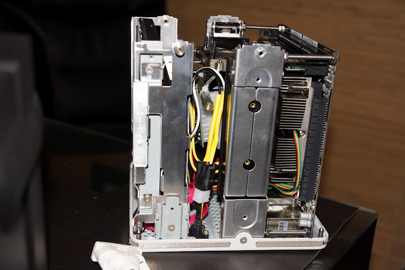
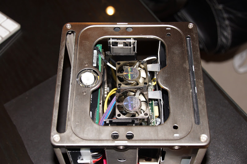
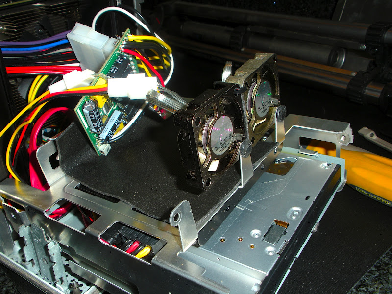
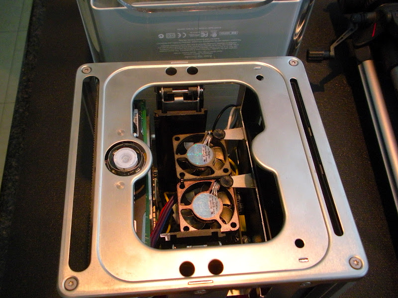
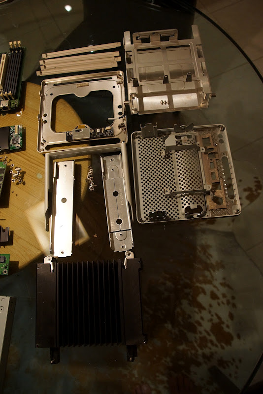
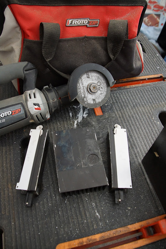
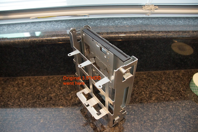
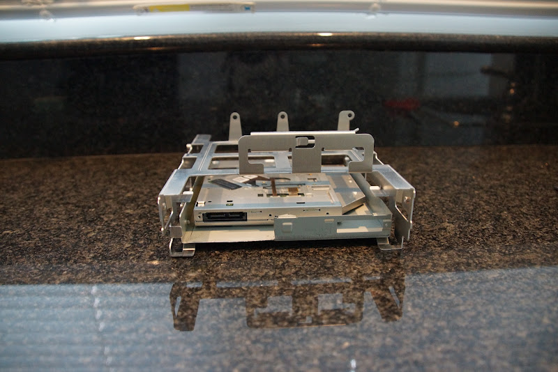
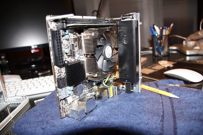
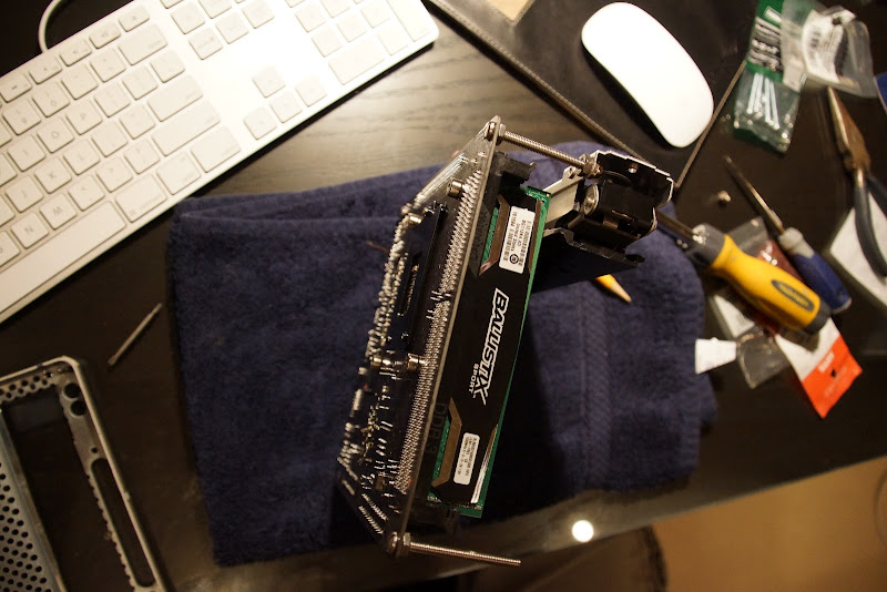
A closer look at the stuff that will make it into the build:
Making it pretty...
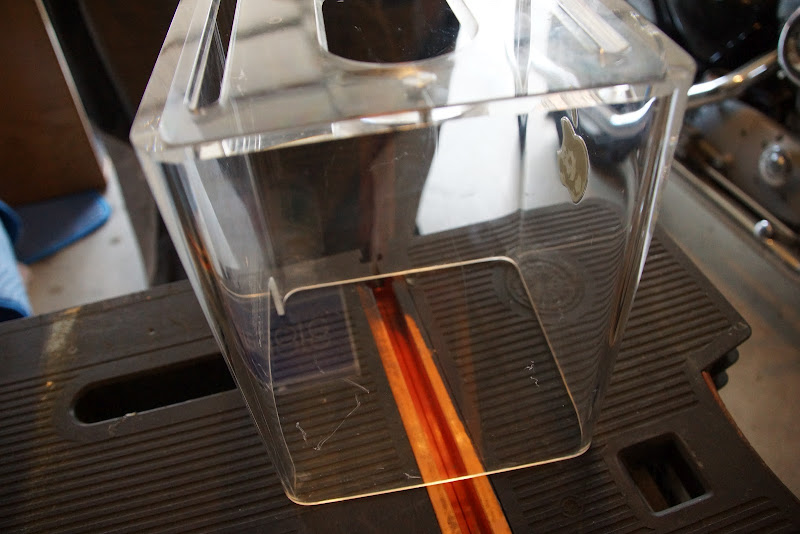
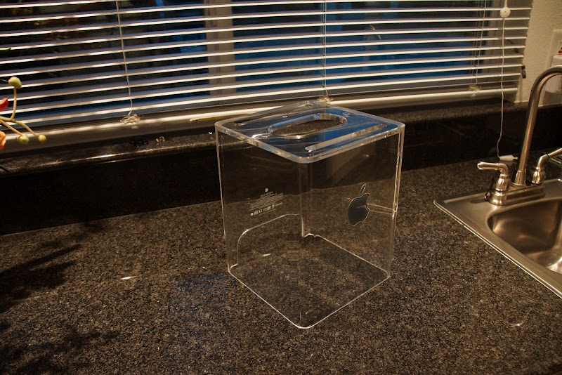
In reality, the Lexan case was scratched up worse than what was shown in the eBay pics. I was sort of bummed:
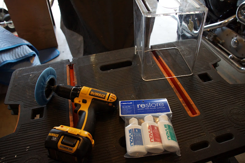
But after a little research, I found a collection of Lexan polishing compounds at The Container Store: Novus® Plastic Polish Trio
Got a buffing wheel for my drill & went to town - first, with the most coarse compound to help remove the heaviest scratches, then the 2nd compound to start refining the finish; finally the high-gloss polish to finish it off:
Voila!
To be continued....
SOOoo... found this G4 Cube on eBay in the local DFW area and began the deconstruction:
Began gathering my build components:
ASRock H77M-ITX LGA 1155 (Intel H77 HDMI SATA 6Gb/s USB 3.0) Mini ITX Intel Motherboard
http://www.newegg.com/Product/Product.aspx?Item=N82E16813157311
Intel Core i5-2500K Sandy Bridge 3.3GHz Quad-Core Desktop Processor Intel HD Graphics 3000
http://www.newegg.com/Product/Product.aspx?Item=N82E16819115072
Crucial Ballistix sport 8GB 240-Pin DDR3 SDRAM DDR3 1600 (PC3 12800) Desktop Memory
http://www.newegg.com/Product/Product.aspx?Item=N82E16820148540
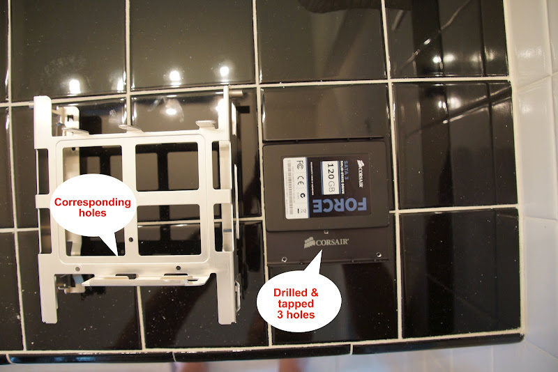
Corsair Force Series 3 CSSD-F120GB3A-BK 2.5" 120GB SATA III Internal Solid State Drive
http://www.newegg.com/Product/Product.aspx?Item=N82E16820233206
Updated: Sony Optiarc Slim Slot-loading Combo Blu-ray Combo Drive Model BC-5650H-01
http://www.newegg.com/Product/Product.aspx?Item=N82E16827118070
GELID Solutions Slim Silence i-Plus (CC-SSilence-iplus) 75mm Ball Bearing CPU Cooler
http://www.newegg.com/Product/Product.aspx?Item=N82E16835426028
Mini-Box PW-200-M, 200w output, 12v input DC-DC Pico Power Supply, with optional P4-ATX Cable
http://www.mini-box.com/PW-200M-DC-DC-power-supply
Mini-Box Model: STD-12160 AC-DC 12V / 16A Switching Power Adapter (100/240V)
http://www.mini-box.com/12v-16A-AC-DC-Power-Adapter
SilenX IXP-11-14 40mm Case Fan (2)
http://www.newegg.com/Product/Product.aspx?Item=N82E16835191001
EDIT: Added Sabrent Mini Bluetooth USB 2.0 Wireless Adapter - model BT-USBT
http://www.frys.com/product/6103319
Already owned:
Apple Wired Keyboard
Apple Wired Mouse
Background on my motherboard choice...
The reason I went with the ASRock board is because I wanted to try & orient the motherboard close to the original position & eventually try getting the touch-sensor power switch/power LED functional.
Most every other board I found (like Gigabyte) had the DIMM slot almost flush with the edge of the circuit board. I was trying to minimize interference issues. A few other ASUS and ASRock boards that had a bit more space between edge of board & DIMM also had the ATX connector just a bit too close & taking up some of the space I felt I needed.
My BIGGEST challenge to date is that there is no current DSDT file in the TonyMacx86 database. Worse yet, there is no patch (yet) in Maldon's site either. So it's been pretty painful getting a fine-tune build.
...and now, on with the show! Just for yucks, here's a shot of the G4 guts completely disassembled:
98% of the stuff at the top half of the pic is unusable. The stuff at the bottom are the key components of the "cage" that will hold all the updated components.
A closer look at the stuff that will make it into the build:
Making it pretty...
In reality, the Lexan case was scratched up worse than what was shown in the eBay pics. I was sort of bummed:
But after a little research, I found a collection of Lexan polishing compounds at The Container Store: Novus® Plastic Polish Trio
Got a buffing wheel for my drill & went to town - first, with the most coarse compound to help remove the heaviest scratches, then the 2nd compound to start refining the finish; finally the high-gloss polish to finish it off:
Voila!
To be continued....


")