- Joined
- Apr 27, 2015
- Messages
- 78
- Motherboard
- Asus Maximus X Hero
- CPU
- i9-9900K
- Graphics
- Vega 64
After putting together a video editing hackintosh earlier this year, I’ve been wanting to put together a second hackintosh to serve as a render node for Final Cut Pro X distributed encoding. I had been planning on a mini-ITX build to keep the form factor small. In the process of looking at mini-ITX boards on various forums, I stumbled on several threads in this forum with iMac G4 case mods, and was intrigued by the ingenuity and creativity I saw in the different approaches to the case mods. Since I still had a 17” iMac sitting the closet which had died several years ago, I thought it would be fun to see if I could squeeze a maxed out socket 1150 build into the iMac G4.
This list is by no means inclusive, but some of the threads/websites that were helpful:
Thanks to all the contributors of the various threads in this forum, which made it much easier to complete this build
I knew power and cooling would be the main limiting factors in how fast of a setup I could squeeze into the half dome of my G4 iMac, and that things like keeping the PSU completely internal and maxing my 4790K overclock to 4.8 GHz, would probably be unrealistic goals. I also knew that aspects such as cosmetics or preserving the DVD drive would probably have to be sacrificed in order to getting the fastest components into the build:
Major Components
- iMac G4 17" 1GHz
- Asus z97i-plus mini-ITX motherboard
- i7 4790K, overclockable to 4.8GHz
- Dynatron K666 CPU cooler
- HD Plex 250 DC-DC PSU, powered by a Dell 330 watt AC power adapter
OSX Yosemite via Clover bootloader
- Audio enabled with toleda's method
- Onboard wifi and bluetooth enable with toleda's method
- Ethernet enabled with IntelMausiEthernet kext
iMac Monitor
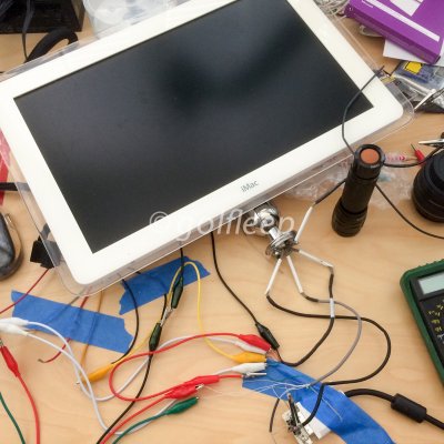
When I had shelved the iMac six years ago, the monitor would not wake from sleep and was getting dim. For those that might need a little help with the tear down, this service guide might come in handy. Dremeljunkie's website and mactester57's thread were invaluable in helping me to successfully breakout the iMac’s video and inverter connections.
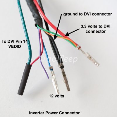
I initially used the Molex right angle DVI PCB connector 74320-4004 as suggested in dremel junkie's guide. However I eventually found and used a straight version of the connector 74320-5004, as I felt it gave a more streamlined connection and allowed everything to be more inline.
Once I confirmed the monitor was working properly, the power connections for the inverter board were terminated with molex connectors, instead of using the alligator clips during the testing phase. The 3.3 volt and ground wires from the DVI connector above were combined with the 3.3 volt and ground wires for the inverter, the VEDID from the DVI connector was also brought over and spliced with the red inverter wire. The purple wire was left floating. I also chose not to enable monitor dimming as described in mactester57's thread, so the green wire was connected to 3.3 volt. The monitor is seen as a built-in display under OS X:
Mockup & component fitting
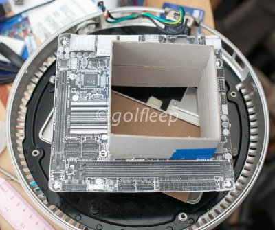
I used cardboard mockups to narrow down the setup and to see what would fit. I initially had hoped to keep everything internal but with the priority being CPU performance, I knew I would need a PSU that could deliver at least 250watts, which pretty much ruled out the picoPSU’s. I ended up going with HD Plex 250 DC PSU, knowing that it would to require me to use an external 19v AC adapter. The HD Plex 250 is rated at 250 watts continuous/400 watts peak, so I knew I would have some headroom to overlock my 4790K.
The mockups also allowed me to test fit different CPU coolers. Both the Noctua L9x65 and Dynatron K-666 fit well, but when I bench-tested the CPU coolers in open air, the Dynatron gave me the lower temps (but was noisier). All of the CPU coolers came pretty close to the opening of the faraday cage dome. There was still room for a Noctua 92 x 14 mm fan, but it required me to come up with new fan mounting brackets as the original iMac fan brackets were designed for a 25 mm thick fan, which would prevent the CPU cooler from fitting.
Baseplate modifications
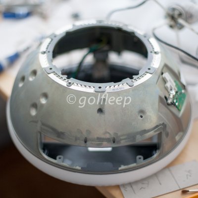
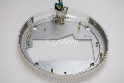
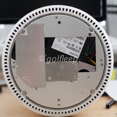
I trimmed the baseplate to allow the PSU to sit as low as possible, which it turn would maximize the room between the top of the CPU cooler and the 92 mm case fan. The motherboard was elevated about 25 mm off the baseplate floor with standoffs that I mounted into tapped M3 holes in the baseplate. A few small sheets of aluminum were added below the trimmed baseplate to support the PSU. The sheets were positioned carefully so that the outer base cover would still fit.
iMac motherboard and rear I/O modifications
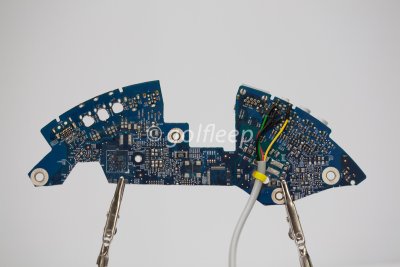
In order to keep the iMac rear I/O panels, most of the original motherboard was trimmed off other than what was needed to mount the rear ports. After cutting the motherboard, the ports that were going to be rewired were removed with a heat gun.
Speaker jack
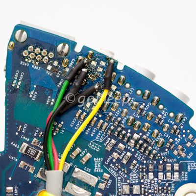
The original speaker jack was retained so that the original iMac speakers could be used. The output of the amplifier board (more details below) was wired to the pins as shown, this information was found in mactester57's thread listed above.
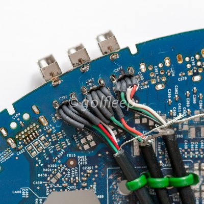
USB 2.0 Ports
The 5V and ground pins of all three USB ports are internally bridged. In order to separate them out, the motherboard was drilled out at the PCB mounting points. This allowed room to solder on short USB extensions (made from old USB cables) in order to extend the mini-ITX motherboard USB ports to the ports on the rear of the iMac.
The 5V and ground pins of all three USB ports are internally bridged. In order to separate them out, the motherboard was drilled out at the PCB mounting points. This allowed room to solder on short USB extensions (made from old USB cables) in order to extend the mini-ITX motherboard USB ports to the ports on the rear of the iMac.

USB 3.0 Port
The two firewire ports next to the USB 2.0 ports were also removed, and in their place, a short USB 3.0 extension cable was glued to provide a USB 3.0 port on the iMac's rear I/O.
The two firewire ports next to the USB 2.0 ports were also removed, and in their place, a short USB 3.0 extension cable was glued to provide a USB 3.0 port on the iMac's rear I/O.
Ethernet Port
I initially though I would be able to use the original ethernet port by simply soldering an extension onto the pins, but I quickly found out during testing that the original motherboard only supports 10/100 ethernet. Just like the USB ports, several of the ethernet jack pins were bridged within the motherboard, which disabled gigabit ethernet. Like the USB port, I had to pull the ethernet jack from the motherboard, drill out the PCB mounting area and then solder the extension directly to the pins. This enabled functioning gigabit ethernet.
I initially though I would be able to use the original ethernet port by simply soldering an extension onto the pins, but I quickly found out during testing that the original motherboard only supports 10/100 ethernet. Just like the USB ports, several of the ethernet jack pins were bridged within the motherboard, which disabled gigabit ethernet. Like the USB port, I had to pull the ethernet jack from the motherboard, drill out the PCB mounting area and then solder the extension directly to the pins. This enabled functioning gigabit ethernet.
Power switch
Use of the iMac's original power switch was retained. A front bezel wiring kit was used to provide the motherboard board connector and wiring. The wires were soldered directly to the PCB connections of the power switch on the original iMac motherboard.
Use of the iMac's original power switch was retained. A front bezel wiring kit was used to provide the motherboard board connector and wiring. The wires were soldered directly to the PCB connections of the power switch on the original iMac motherboard.
DC Power Jack
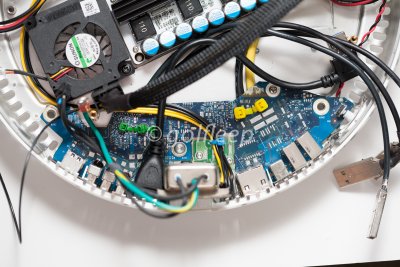
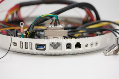
The final I/O modification was for the 7.4 mm DC jack for the HD Plex 250 PSU. The old modem port was the perfect size for the DC jack. Even better, the phone jack is mounted to a separate small PCB, which made it easier to modify to hold the DC jack. I did have to use a bit of epoxy to make a spacer to prop up the DC jack to line up with the I/O panel of the iMac.
The final I/O modification was for the 7.4 mm DC jack for the HD Plex 250 PSU. The old modem port was the perfect size for the DC jack. Even better, the phone jack is mounted to a separate small PCB, which made it easier to modify to hold the DC jack. I did have to use a bit of epoxy to make a spacer to prop up the DC jack to line up with the I/O panel of the iMac.
HDPLEX PSU, Amplifier, and SSD Mounting
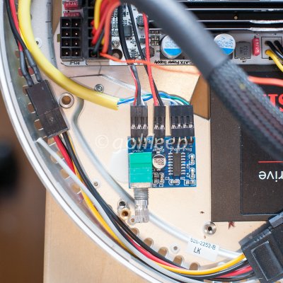
The PSU, amplifier board, and SSD were all mounted underneath the motherboard. The PSU was mounted so that it's connectors would be clear of the motherboard, in order to keep things as vertically compact as possible. A small 5V laptop fan was mounted to direct airflow over the heatsink of the PSU. The amplifier board is a 2 x 3watt board based on the PAM8043 chip. Initially, I had background noise issues that were probably due to grounding issues. This was resolved by grounding the amplifier board as close as possible to the ALC892 chip in the motherboard - I ended up using the motherboard mounting screw right next to the ALC892 chip. (see below)
WiFi and Bluetooth antennas
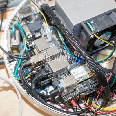
The iMac's built-in antenna connectors were not compatible with the standard antenna connectors, so a pair of laptop antennas were used, the antennas were placed outside of the faraday cage, underneath the outer plastic shell of the iMac, with the wiring routed through the faraday cage in the same manner as the original wiring.
Trimming the PSU wires
In order to make things as compact as possible and to facilitate putting the two halves of the iMac chassis together, The ATX and CPU PSU wiring was trimmed and sleeved, so there wouldn't be any loops to contend with. Items needed to work with ATX connector wiring:
- Molex mini-fit jr extractor, Molex part 11-03-0044
- mini-fit jr pins, Molex part 39-00-0039
- Molex mini-fit jr crimper, Molex part 63811-1000
Final assembly
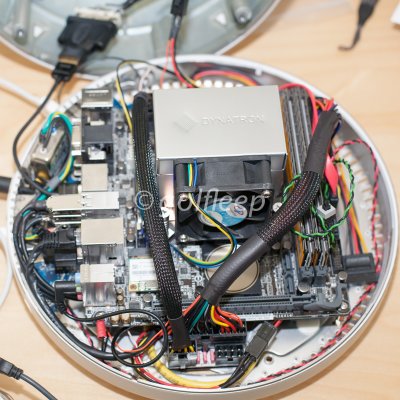
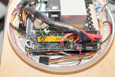
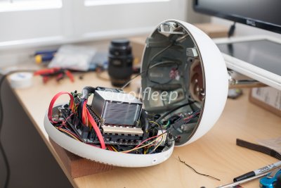
The mini-ITX motherboard sits directly on top of the PSU. You can see how the end of the PSU extends past the motherboard to allow the PSU connectors to fit it, and by shortening and sleeving the PSU wiring, things are much more compact.
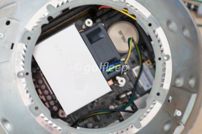
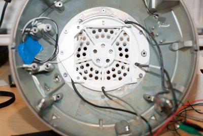
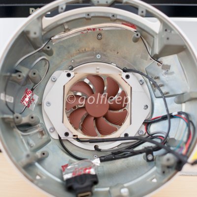
To simplify the monitor wiring, the inner white fan/wiring bracket was drilled out to let the monitor wires exit directly. A Noctua 92 x 14 mm fan was necessary because of clearance issues with the CPU cooler, this also meant the stock fan brackets would not work, instead I had to construct custom fan brackets from flat aluminum stock. With the custom brackets, the base of the fan sits flush against the the bottom of the video wiring bracket/fan holder. In the second picture, the finalized DVI/HDMI connector is in the bottom center and the (blurred) power connector is to the bottom left. The wifi/bluetooth antennas were routed and secured from one side of the chassis to the proximity of the motherboard wifi connections.
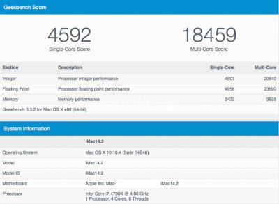
Benchmarks
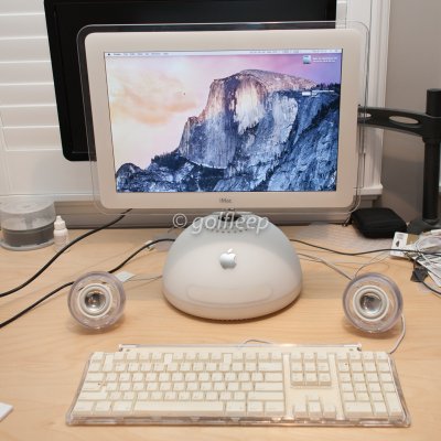
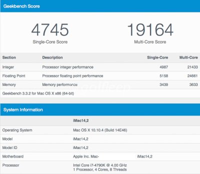
All in all, I have been very satisfied with the results, and had a lot of fun putting together the build. I can run the 4790K at 4.6 GHz and keep CPU temps in the 75-80° range. I did have to resort to using a large and heavy external AC power brick, and I did lose use of the DVD drive. The CPU cooler I ended up using is a bit noisy as well. Nevertheless, because I was able to retain most of the original ports and use the original speakers, the computer looks pretty much like it did prior to the mods. Even better, it essentially performs the same as my other hackintosh, allowing me to perform distributed encoding tasks in about half the time as with a solo computer.

