You are using an out of date browser. It may not display this or other websites correctly.
You should upgrade or use an alternative browser.
You should upgrade or use an alternative browser.
- Status
- Not open for further replies.
- Joined
- Nov 20, 2012
- Messages
- 166
- Motherboard
- Asus Maximus Viii Gene
- CPU
- Intel i7 6700k
- Graphics
- Evga 980Ti Classified
- Mac
- Classic Mac
- Mobile Phone
hi! can you please help me with the soldering points of the rear panel? i really want to do the same for the rear panel as i don't want to cut any part of the casing. i hope you can give me color coded wires + soldering point for the optical out, audio and mic, usb 1 and 2 and ethernet.
i really anyone can help as im also doing my mac g5 project.
i really anyone can help as im also doing my mac g5 project.
- Joined
- May 28, 2017
- Messages
- 32
- Motherboard
- MSI B85M-E45
- CPU
- Xeon E3-1230 V3
- Graphics
- GT 740
- Mac
- Mobile Phone
Hi, nice mod. 2 thing about the PSU as I will mod mine too.About the PSU:
I did it just out of curiosity. Based on what I saw on the forums, I set my expectations low. I knew that architecturally it isn't very different from an ATX one with most demand from the 12V lines, but I wasn't sure about any implementation differences. I planned from the beginning to use a PicoPSU, but I had to order it online (I have received it in the meantime; still need to find a good inexpensive 120W power brick).
The PSUs I had lying around were probably as old as the one from the G5, so I didn't want to bother with them, and I thought that with 600W available, even at 60% efficiency at 40-100W typical loads, it's going to be ok, so why not try it. If it doesn't work, it's going to delay me several days until the parts arrive, and if it does, then I wouldn't need to do any modifications to the wiring for the hard drives, nor mounting the powerbrick and rerouting AC leads, and that kind of stuff. I can do those things later incrementally.
I didn't make any internal pictures of the PSU, but you can zoom in the picture of the working computer with the PSU outside the case. I can take a picture later when I replace it with a PicoPSU if there's interest.
Basically, I had to split the ATX wires to P1 and P2 connectors. The extension cable that I used for testing was so confusing with different colors, so I had to check the connections several time before I finally swithced it on. For this test I took the 4-pin CPU cable from the P3 connector, which reduced guesswork, but I used it from P2 in the final build.
After the test, I cut off the ATX cable from an old PSU, and connected it directly to the P1 and P2 connectors. I soldered the ends of wires to correct thickness, and I plugged them into P1 and P2 connectors. It's quite secure. I'm not sure how difficult it would be to draw the diagram, but if used G5 and ATX diagrams found on this forum and other places on the net, and I consulted the official ATX specification document (I can't search for it now, but it should be easy to find).
In a nutshell, the color coding is almost identical: black is GND, yellow in 12V, red is 5V, orange is 3.3V, PWR_ON signal is green, -12V is blue, not sure if I'm forgetting anything. -5V on ATX can be ignored. The only thing that I wasn't sure about was the Power OK signal. ATX documentation says the PSU sends 5V on it once the voltages have stabilized (which is often implemented by a simple timer, and not by any measurements) and, in theory, turns it off in case of a brown out. The motherboard then keeps the CPU in reset state while this signal is inactive. They recommend (to PSU builders, I guess) not just connecting the regular 5V signal, because it would have to drop to about 2.4V or so before the motherboard would interpret it as inactive.
The G5, apparently, doesn't do this, at least to my knowledge, so I thought the risk would be low if I do exactly that (connect a red 5V line to this pin), and that's exactly what I did, and probably what many cheap PSUs do anyway.
Another item that needed attention was the 12V line. There is a single 12V pin on the ATX 20 connector (and two more on the 24 pin), which comes from P1. The 4-pin CPU cable gets it from a separate 12V source. On the P2, it's the yellow lines closest to the 25V line. So, in summary:
P1: GND, -12V, PWR_ON, (anything else?) to corresponding pins on ATX20 (and perhaps GND to ATX4)
P2: 5V, 3.3V, 12V_v2 to corresponding pins on ATX20; 12V_v3 to ATX4; also 5V to PWR_OK on ATX20
P3: direct to optical and hard drives
Nick, I thought the steel parts showed some finger marks, too, but, overall, I was amazed how clean and dust-free the whole computer was.
And, MacTester, since this is my wife's computer, it had to be Windows. But she loves the galaxy background.
On P1 there is the 5v Sense. Wouldn't it be better to connect the PWR OK to this Pin? I think it has the same feature. And how die you connect the 3.3 V Sens option (brown cable)? Did yo join the cables (orange+brown)?
- Joined
- Jan 15, 2017
- Messages
- 4
- Motherboard
- GA-Z170X GAMING 5
- CPU
- Core i7-7700K
- Graphics
- EVGA GTX 970 SC 4GB
- Mac
- Classic Mac
- Mobile Phone
Has anyone worked out how to keep the rear I/O looking this clean? This mod seems to be soldering onto the original board. Does it require a controller board to connect to a modern ATX motherboard?
- Joined
- Sep 8, 2017
- Messages
- 24
- Motherboard
- Asus prime b350m-a
- CPU
- Ryzen 3600x
- Graphics
- Radeon RX5700
Has anyone worked out how to keep the rear I/O looking this clean? This mod seems to be soldering onto the original board. Does it require a controller board to connect to a modern ATX motherboard?
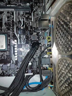
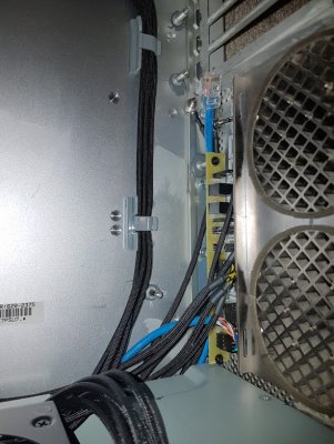
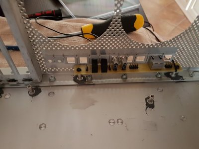
Just finishing my own mod, w/ stock outside look. Need to optimize routing (make it nice ;-), make some pictures of final look and will prepare complate build report, just don't have much time now (expect after christmas could be done).
I made my own Rear IO PCB. Some pictures how it looks like.


- Joined
- Jan 15, 2017
- Messages
- 4
- Motherboard
- GA-Z170X GAMING 5
- CPU
- Core i7-7700K
- Graphics
- EVGA GTX 970 SC 4GB
- Mac
- Classic Mac
- Mobile Phone
I made my own Rear IO PCB. Some pictures how it looks like.
Very very nice. I look forward to your detailed build notes, hopefully with sources for items (if any).
All the best through the holiday period.
- Status
- Not open for further replies.
Copyright © 2010 - 2024 tonymacx86 LLC
