Contribute
Register

G4 Quicksilver switch

Status
Not open for further replies.
hey there!

i'm also in a process of doing a quicksilver conversion.
unfortunately the images in this thread don't show up for me.

does anyone know what's up with that?

thanks!
 
TYVM!! This old thread still comes in handy, worked like a charm! I was worried something wouldn't work as some of the resistors flew off when my screwdriver slipped scraping off the chip on the board. all is well!
 
Yes, if you want power switch you have to do a bit of soldering. That's because there is no direct connection on the cable to the positive (+) side of S1 (the switch on the board) - so you must solder a wire to there as a minimum. To be honest, this switch is a bit of a pain and it may be easier just to do a full hot wire to it ( I mean soldering wires directly to what you need on the board and forget about the ribbon cable).

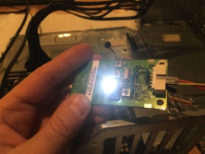
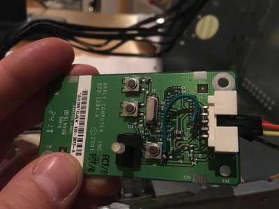
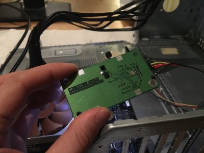
IMG_7806.JPG IMG_7807.JPG IMG_7808.JPG

Hi minihack, I need a little help please. My led diode (on the power button) is on all the time as soon as I plug the PC into electricity. I followed your guide, but must have made a mistake along the way. When I unplug the wire connected to PIN 8 (LED negative) the LED is still on.
 
Last edited:
If you still have the LED illuminated when that wire is disconnected then it must be getting a ground ( zero volt return) signal from somewhere else - so you need to scrape away PCB connections adjacent to the negative leg of the LED until it is ONLY accessible via your wire.
 
i soldered the cables direct to the switch an LED and what should i say? Didn't work. After one shutdown with osx i can't start again by push the button. so i desoldered all chips that where on the board. now it worked like charm. A dumb solution but it works.
 
Just here to confirm that this guide worked very well for me!
 
Hi Roto31,

When rigging the switch as in the sawtooth switch thread, for each of the switches, (S1, S2, S3 - power, reset, programming) the result is a simple short between switch + terminal and the ground track on the switch board as that is how the Mac board worked. For the LED it is similar, there is a LED + connection and that is actually connected to the Anode via an onboard 40 Ohm resistance (which does not affect its ability to light fine on my board) and the common cathode connection for that two colour LED is connected to the board ground. There is only one ground connection on the ribbon cable and assuming that on the board you are using all switch negative (-) connections (and the LED - connections) are internally connected to ground on the motherboard end then as long as there is a single ground connection linking the switch board to the mobo all functions should work correctly.

On my conversion I hooked up the power switch + and the common board - (ground) to the power switch + and - terminals respectively on my mobo (which is GA-P55M-UD4) and the LED + connection to the power LED + connection (leaving the LED - connection open/not connected) and the LED and Power switch functions work fine. Holding the power button pushed while the machine is running should have the same effect as holding a regular power switch pressed - i.e. if a normal PC momentary switch produces hard shutdown then doing that with the modded Mac switch will do the same - in the end it is just a regular momentary switch.

I have not hooked up the reset + or the programming switch +, but if my assumption that the mobo uses a "switch to ground" connection is correct then there is no reason why hooking those up would not work. You can verify if the mobo works that way by just doing a simple multimeter test (with power disconnected from the machine) to check if there is zero resistance between reset switch - connection and ground. If there is, then the mod will work, if there is not, then it won't......and in that case then it is better instead to do a full hot wire and to cut traces on the switch board to remove all of the common grounding between the switch connections. I'll do a multimeter check later on my boards just to verify what the status is of the negative sides of the various connections to see if they are indeed all connected to a common ground level.

Can you show a diagram or pictures of your mod?


I'm trying to keep my mod as vanilla as I can, and really want to be able to get the power button to work as it did originally. It appears that on mine (820-1178-A), there is no pinout connected directly to the power switch. Pushing power button does nothing. Currently, I only have the reset button connected to Power-button motherboard header instead.

To use the front-panel speaker, I pulled apart a usb headset cable for the little sound card on it. Then I soldered that to a tiny USB amp for a USB speaker. Then I wired that to the speaker. So, my front-panel speaker is powered off one of the USB headers of my motherboard. The components are tucked neatly away in the speaker casing. I'm willing to do something similar in order to get my power button and led to function as well.

Any ideas or resources you can point me to?
 
Hej,

about the power switch at the Quicksilver front panel board (820-1284-A):
It is only working if 5V is supplied at Pin4 and GND on Pin8 or Pin7:
If at least Pin7 is Connected to ground and only with a multimeter connected to ground and S1+ the power LED lights up when S1 is pressed, and fades out on release.

1. S3+ Programming switch - works always
2. unknown maybe NC
3. S2+ Reset switch - works always
4. 5V+ This goes to the Anode (+) of the LED but also to the + power terminal of the microcontroller;
5. S1+ Power switch - works if 4 is connected to 5V
6. unknown maybe NC
7. Ground - gnd power terminal of the microcontroller
8. Common Ground
9. Not connected
10. This is connected to one of the pins on the microcontroller, probabbly the +0.5v Status Line

right now I dont get how the MC on the Front Panel gets to now that the mac/PC is running,
one of the other panel schematics mentions a +0.5V Status signal... (http://www.outofspec.com/frankenmac/wire.shtml)
 
Last edited:
Status
Not open for further replies.
Back
Top