- Joined
- Jun 29, 2013
- Messages
- 9
- Motherboard
- Gigabyte - Ga-Z87M-D3h
- CPU
- Intel i5-4570 3.20 Ghz
- Graphics
- Asus Nvidia GeForece GTX 760 Direct2 OC
- Mac
- Classic Mac
- Mobile Phone
Hello Minihack,
I hope that you are fine.
The reason i reply to your thread is that i need your help if you don't mind.
I have the MDD G4 Case and i want to convert it to a miniAtx motherboard.
I have some problems with the power ON / OFF button switch wires.
What i have to do to connect it to my new motherboard Gigabyte H87M-D3H ?? I have to chenge the wires or is ok like that?
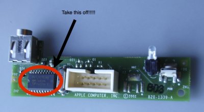
That`s the power switch (on / off button cable)


I hope that you can help me !!
Thanks a lot in advance!
Best
I hope that you are fine.
The reason i reply to your thread is that i need your help if you don't mind.
I have the MDD G4 Case and i want to convert it to a miniAtx motherboard.
I have some problems with the power ON / OFF button switch wires.
What i have to do to connect it to my new motherboard Gigabyte H87M-D3H ?? I have to chenge the wires or is ok like that?
That`s the power switch (on / off button cable)
I hope that you can help me !!
Thanks a lot in advance!
Best