- Joined
- Oct 14, 2015
- Messages
- 68
- Motherboard
- Gigabyte Z170MX-Gaming-5
- CPU
- i7-6700K
- Graphics
- W5500
- Mac
- Mobile Phone
I came across this HP Z400 Workstation with a busted motherboard from my previous job. It was out of warranty so it'd have been thrown away. So I thought I would rescue and make use of it. I was tired of my current case which didn't dissipate the heat very well.
I first opened up the case and took everything out. All the screws have a Torx-15 bit. So you'd need a T15 bit. Then I found out this HP workstation comes with a proprietary motherboard and PSU.
You'll need to mod the case to mount a standard ATX PSU. The PSU connector pinout is also different from a standard ATX 24 pin. The PSU looks pretty decent, with 456W on 12V, which is more than enough for my build:

So I decided to mod the PSU instead of the case. I found the pinout, side by side with a standard ATX and verified with a multimeter:
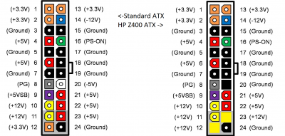
Since -5v(pin20) is only for legacy ISA which I don't have and no modern PSU implements it, I only need to change 2 pins: pin 12 (12v->3.3v) and pin 23(12v -> 5v). I can draw them from a SATA connector or from other pins on the main connector. It makes no difference to the PSU, as long as the cables can handle the current. 5v and 3.3v on the motherboard are used to power the RAM, chipset, and PCI. I don't have anything power hungry, only a low end video card and a Wifi/BT combo card. So I figured I'd just draw from the main connector, by using an extension cable. I just snipped those two wires and soldered onto two other pins.
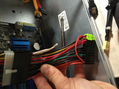
Then I used the multimeter to test it without hooking up with a motherboard. You need to use a paper clip to gound PS_ON (pin 16) to turn on the PSU manually. The PSU also has a 4 pin CPU connector instead of 8 pin. But my motherboard accepts the 4 pin connector just fine with the other 4 pins empty. My CPU (i7 950) doesn't draw that much current anyway.
The motherboard is full ATX size. It sits on a tray that snaps onto the case. But the mounting holes are a little different from a standard ATX. In the following picture, only the ones circled match standard ATX.

Upon further investigation, I found pre-drilled holes on the frame that look like they match ATX layout. So I measured them against the ATX spec (http://www.formfactors.org/developer\specs\atx2_2.PDF). They sure match up!
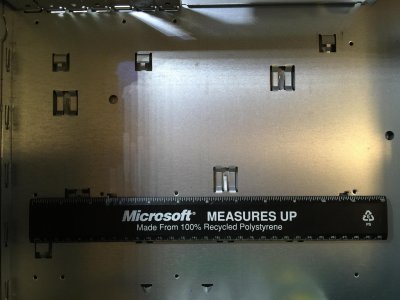
The holes are actually friction drilled so they are a little thicker than the sheet. But they don't have threads. So I tapped some 6-32 threads so that I can screw some standoffs on them.
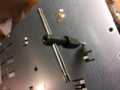
To do that, I needed to take the whole case shell off so that the tapping tool could go through. Some holes are easier to tap from the outside anyway. There are four small counter sunk screws with Torx-8 head. I borrowed a T8 bit from our IT guy to remove those screws. You can replace them with standard Philip head screws. The threads are standard 6-32.
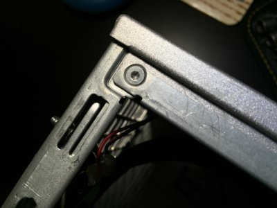
After tapping all the holes, I screwed on some 6mm standoffs and mounted an ATX motherboard. It aligns very well.

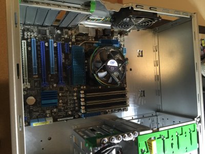
At this point, I put the PSU back into the case and verified everything was working. I didn't have the front panel hooked up yet. But my motherboard has a power button on the board. Otherwise you could use a screw driver to short the pins.
The next steps were to hook up the panel and reuse the CPU cooler. The CPU cooler looks pretty nice and it comes with a very quiet fan, compared to the crappy stock cooler that came with the CPU. The stock cooler uses plastic clips to snap onto the motherboard. The Z400 cooler is screwed onto the motherboard tray. Since I'm not using the tray, I'd need a backplate. But I decided not to spend those $5 to buy a backplate for this 6 year old motherboard. So I just used some nuts and washers.
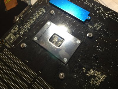
Now another weird thing about this cooler is that the fan comes with a 5-pin connector instead of a standard 4-pin one. Two of the ground pins are actually shorted together (what's the point?). So I just removed the pins from the connector, snipped the extra ground pin, and put them in a 4 pin connector I happened to have. If I didn't have the connector, I'd have simply ground off the extra hole on the connector.

Note that the official service guide of Z400 has the pinout wrong. The correct pinout is:
black: ground
yellow: +12
green: tach
blue: PWM
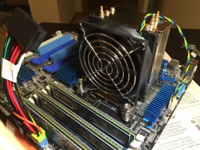
Motherboard with the new cooler installed:
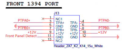
Now the only thing left is the front panel connectors. The front panel of Z400 has two USB ports, one ac97 audio port, one Firewire 1394 port, Power switch, HDD LED, and Power LED. There is no reset button (HP doesn't think their computers would ever freeze up). The USB and audio ports have standard connectors. I just plugged them to the headers on the motherboard. The Firewire port is a weird 14 pin connector. I found the pinout from the HP forum but didn't bother setting it up. I have never owned a Firewire device.
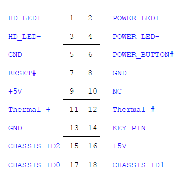
The power switch, LEDs, along with a thermal sensor share a 18-pin connector that goes to the motherboard. don't have use of the thermal sensor. Here is the pinout of the connector. Pin-14 is a key pin (plugged) used to identify the direction.
The speaker is on its own connector. I didn't bother to hook it up. I just pulled pins out and put them in a 20-pin connector, since my motherboard (Asus) has a 20 pin header. I guess you could just reuse the 18 pin connector if you are not using both ends of pins. You could also use a Q-connector if you have an Asus motherboard. Before pulling out the pins, it'd be helpful to label the wires to save some guess work later on.

All done, with 2 SSDs dual booting El Capitan and Windows 10, one HDD for user data. You will need some work to get the I/O shield fit in the opening. I didn't bother.

You can also mount an mATX board but you will not be one standoff short, since mATX has an extra hole and the case doesn't have it. It's not a big deal. But if you really want, you can just friction drill it yourself, or drill through and use a female-to-female standoff and a screw on the other side.
I first opened up the case and took everything out. All the screws have a Torx-15 bit. So you'd need a T15 bit. Then I found out this HP workstation comes with a proprietary motherboard and PSU.
You'll need to mod the case to mount a standard ATX PSU. The PSU connector pinout is also different from a standard ATX 24 pin. The PSU looks pretty decent, with 456W on 12V, which is more than enough for my build:

So I decided to mod the PSU instead of the case. I found the pinout, side by side with a standard ATX and verified with a multimeter:

Since -5v(pin20) is only for legacy ISA which I don't have and no modern PSU implements it, I only need to change 2 pins: pin 12 (12v->3.3v) and pin 23(12v -> 5v). I can draw them from a SATA connector or from other pins on the main connector. It makes no difference to the PSU, as long as the cables can handle the current. 5v and 3.3v on the motherboard are used to power the RAM, chipset, and PCI. I don't have anything power hungry, only a low end video card and a Wifi/BT combo card. So I figured I'd just draw from the main connector, by using an extension cable. I just snipped those two wires and soldered onto two other pins.

Then I used the multimeter to test it without hooking up with a motherboard. You need to use a paper clip to gound PS_ON (pin 16) to turn on the PSU manually. The PSU also has a 4 pin CPU connector instead of 8 pin. But my motherboard accepts the 4 pin connector just fine with the other 4 pins empty. My CPU (i7 950) doesn't draw that much current anyway.
The motherboard is full ATX size. It sits on a tray that snaps onto the case. But the mounting holes are a little different from a standard ATX. In the following picture, only the ones circled match standard ATX.

Upon further investigation, I found pre-drilled holes on the frame that look like they match ATX layout. So I measured them against the ATX spec (http://www.formfactors.org/developer\specs\atx2_2.PDF). They sure match up!

The holes are actually friction drilled so they are a little thicker than the sheet. But they don't have threads. So I tapped some 6-32 threads so that I can screw some standoffs on them.

To do that, I needed to take the whole case shell off so that the tapping tool could go through. Some holes are easier to tap from the outside anyway. There are four small counter sunk screws with Torx-8 head. I borrowed a T8 bit from our IT guy to remove those screws. You can replace them with standard Philip head screws. The threads are standard 6-32.

After tapping all the holes, I screwed on some 6mm standoffs and mounted an ATX motherboard. It aligns very well.


At this point, I put the PSU back into the case and verified everything was working. I didn't have the front panel hooked up yet. But my motherboard has a power button on the board. Otherwise you could use a screw driver to short the pins.
The next steps were to hook up the panel and reuse the CPU cooler. The CPU cooler looks pretty nice and it comes with a very quiet fan, compared to the crappy stock cooler that came with the CPU. The stock cooler uses plastic clips to snap onto the motherboard. The Z400 cooler is screwed onto the motherboard tray. Since I'm not using the tray, I'd need a backplate. But I decided not to spend those $5 to buy a backplate for this 6 year old motherboard. So I just used some nuts and washers.

Now another weird thing about this cooler is that the fan comes with a 5-pin connector instead of a standard 4-pin one. Two of the ground pins are actually shorted together (what's the point?). So I just removed the pins from the connector, snipped the extra ground pin, and put them in a 4 pin connector I happened to have. If I didn't have the connector, I'd have simply ground off the extra hole on the connector.

Note that the official service guide of Z400 has the pinout wrong. The correct pinout is:
black: ground
yellow: +12
green: tach
blue: PWM
Motherboard with the new cooler installed:

Now the only thing left is the front panel connectors. The front panel of Z400 has two USB ports, one ac97 audio port, one Firewire 1394 port, Power switch, HDD LED, and Power LED. There is no reset button (HP doesn't think their computers would ever freeze up). The USB and audio ports have standard connectors. I just plugged them to the headers on the motherboard. The Firewire port is a weird 14 pin connector. I found the pinout from the HP forum but didn't bother setting it up. I have never owned a Firewire device.

The power switch, LEDs, along with a thermal sensor share a 18-pin connector that goes to the motherboard. don't have use of the thermal sensor. Here is the pinout of the connector. Pin-14 is a key pin (plugged) used to identify the direction.

The speaker is on its own connector. I didn't bother to hook it up. I just pulled pins out and put them in a 20-pin connector, since my motherboard (Asus) has a 20 pin header. I guess you could just reuse the 18 pin connector if you are not using both ends of pins. You could also use a Q-connector if you have an Asus motherboard. Before pulling out the pins, it'd be helpful to label the wires to save some guess work later on.

All done, with 2 SSDs dual booting El Capitan and Windows 10, one HDD for user data. You will need some work to get the I/O shield fit in the opening. I didn't bother.

You can also mount an mATX board but you will not be one standoff short, since mATX has an extra hole and the case doesn't have it. It's not a big deal. But if you really want, you can just friction drill it yourself, or drill through and use a female-to-female standoff and a screw on the other side.
