Contribute
Register

Fans Please STFU !!!

Status
Not open for further replies.

JBG

Joined
Oct 4, 2012
Messages
67
Motherboard
Gigabyte Z77N no working Wifi
CPU
i5-3570K
Graphics
Intel HD 4000
Mac
  1. iMac
  2. MacBook Pro
  3. Mac mini
Classic Mac
  1. Power Mac
Mobile Phone
  1. iOS
NO NOT YOU !! The fan's of ofcourse :p

Please STFU (Shut The FANS Up)
:lol:


Hi all ... I'm back ... and almost finished with my new project ...

I made my mind up to control the fans with a micro controller and a I2C line for the sensors.
I discovered the micro controller a few weeks ago and I like them, the programming too.

I have little experience in electronics and programming from few decades ago o_O ...
so ... picking it up was not so hard for me,
only a big investment in parts (ssst don't tell my wife) ...

If you don't like micro controllers or a little programming, don't read further and use other parts which are available in a lot of stores ... for me it's just a hobby todo this and share it with others...

This is a cheap but good working project, it only took (for me) a little time to figure out a few things and make a comeback in programming.


The Start

It began with searching for controlling my fan's cause I didn't like the way the motherboard does it and my board has only 2 fan port connections :confused:

After a few small projects for sensors and solutions I run into a Arduino Board :banghead:
And with a little experiencing I made it myself and found a easy way of controlling fans.
So the next search and question was ... WHAT kinda sensors to use ...

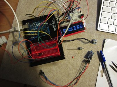
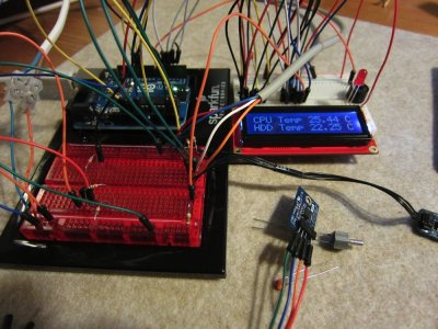
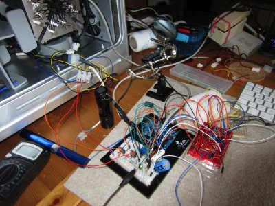
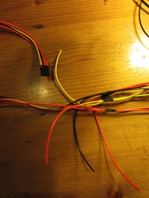
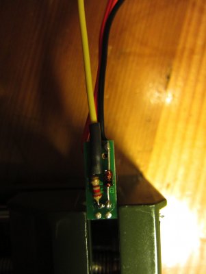
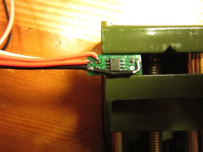
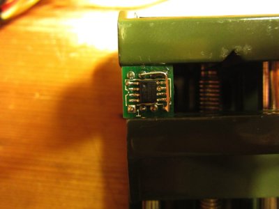
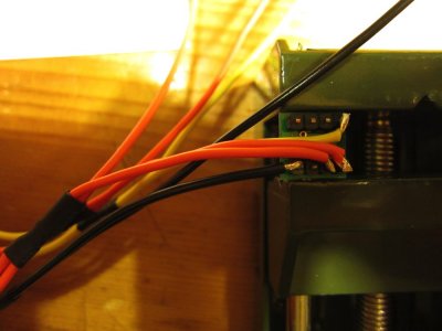
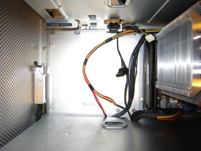
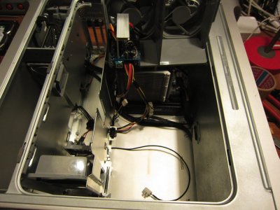
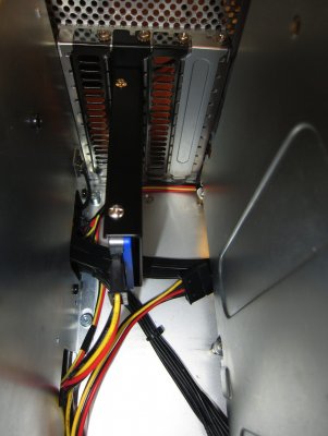
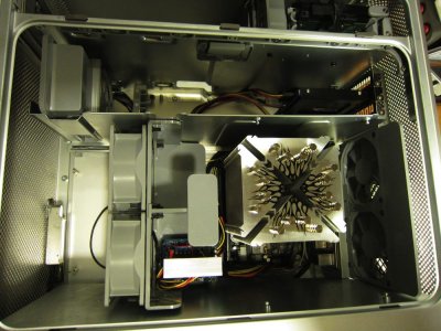
IMG_0266.jpgIMG_0268.jpgIMG_0301.jpg

and I made up my mind to use the TCN75A temperature chip ... why a chip ?
I try to use other type of sensors, but ... sins I'm working with a micro controller it was
easier to use this chip cause of less wiring (4 wires for all sensors, max 8).

I started to figure out how PWM controlling works and that's what I want to use now,
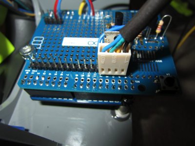
and made a little try-out on a test board and a little sooner after it works on a Arduino Protoshield.
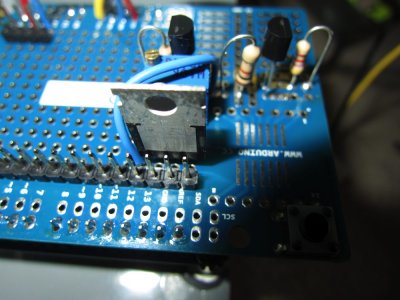
1391_big.png IMG_0311.jpg


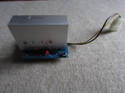
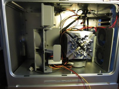
Now I had to find a place and my idea was to I put it all in here (for cooling proportions too):
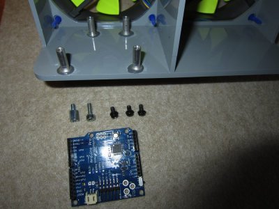
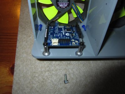
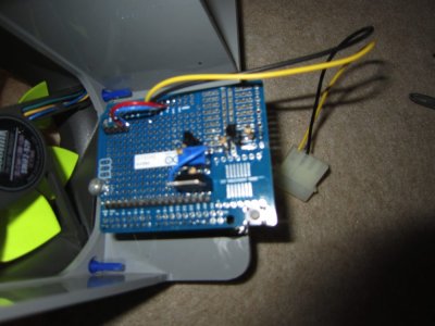
IMG_0308.jpgIMG_0309.jpg
IMG_0310.jpgIMG_0313.jpg

The Change

So ... that was it ... I build it in and ... ready Freddy ...
No ? ... Why not .. ? Ok .. for the people who know me ... I'm not easily satisfied ... so ... due building
I came up with the idea to take a look at the controlling of the original G5 fans, you know ... the once who make a lot of noise ... un-controlled ...

First thing first ... how are they connected ??? no data on it, no colored wires .... mmm ...
So .. after a little testing and waiting for the most smoke was gone now :geek: :mrgreen:
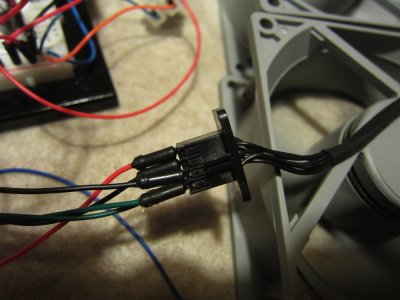
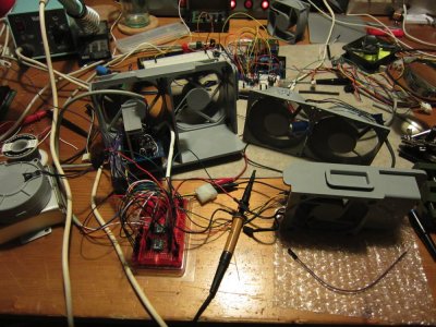
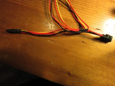
I found out how to use them, so take a look at a few pictures :
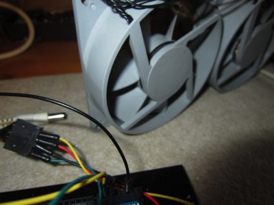
IMG_0316.jpgIMG_0317.jpgIMG_0318.jpg
Ok ... after a little (lot) testing and a lot of smoke (just kidding)
I figured out that is was NOT working at all .... :problem:
If use PWM .. not matter what the PWM frequency is .. they make a HELL of a noise (frequency sound)
Mmm ... plan B ... I tried with normal controlled power 0-12 v and the where excellent controllable :headbang:

But ... now I had to give the protoshield board a whole new direction ... it didn't work with that few parts used.
Ow ... before I forget to tell ... black = 0v, red is 12v, and green and yellow are respectively controlling connections for the left and right fan... the one or two wires left are the tachometric signal(s).

So ... now what .. my Arduino output is PWM and the fans are not ...
I figure out a very easy way to convert a PWM signal into a voltage signal ... just with a resistor, capacitor, transistor and a op-amp (to amplifier the voltage a little)

And after a little testing, burning my fingers, and smoke some hardware :clap:

The Build.


And the next step is .... put it from the experiment board on a protoshield print :
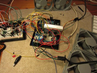

IMG_0319.jpg


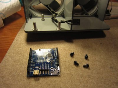
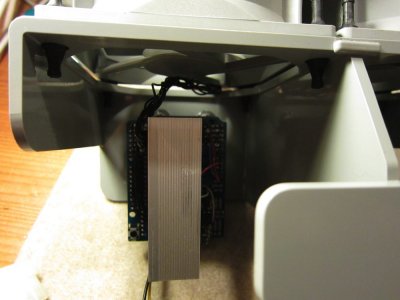
To prepare the fans for placing the Arduino and shield (few pictures of how I did that)​
IMG_0321.jpgIMG_0322.jpgIMG_0323.jpgIMG_0325.jpg

Connect and wire it all for final testing​

IMG_0320.jpg

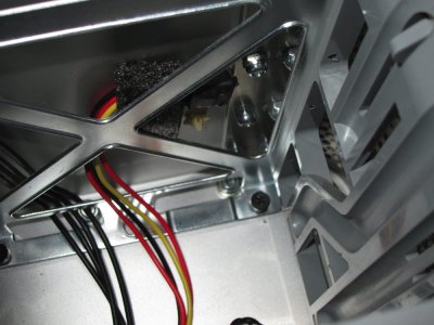
Making the complete wire set for into the G5​

IMG_0326.jpgIMG_0327.jpgIMG_0328.jpgIMG_0329.jpgIMG_0330.jpgIMG_0331.jpg

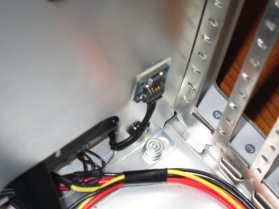
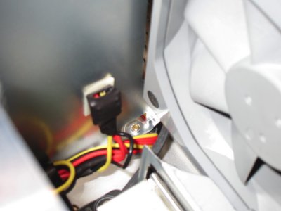
Wire some sensors (I use different SMD breakout boards just for try out what is fine, but use TCN75A on all of them ...

IMG_0332.jpgIMG_0334.jpgIMG_0335.jpgIMG_0336.jpgIMG_0337.jpgIMG_0338.jpg

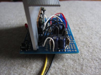
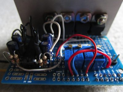
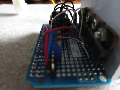
And this is a close up from the protoshield :cool:

IMG_0342.jpgIMG_0344.jpg
IMG_0345.jpgIMG_0347.jpg


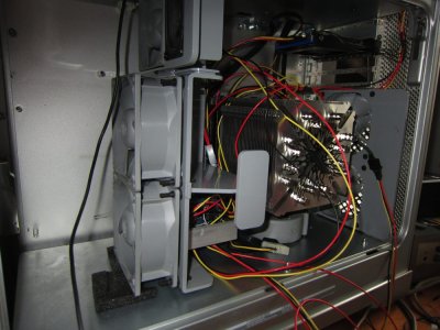
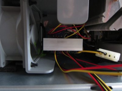
And then I used my feet to get it all into the iHack :angel:

IMG_0339.jpgIMG_0341.jpg


IMG_0348.jpg


So ... that's about all of it ... I made a program for the Arduino...
And a schematic too for the protoshield have fun, and I hope someone tries to make it too ....
It works great ... the fans are adjustable to almost not moving, and when it's getting warm they blow ya hear off ya head ... GL ... HF and happy smoking ...


The Arduino code : <---- Software Update at #5


Code:
  DELETED by JBG (see update [URL="http://www.tonymacx86.com/powermac-g5/92026-fans-please-stfu.html#post565331"]#5[/URL])


Part list Original Fan Controller :


Arduino Board : Arduino Pro 328 - 5V/16MHz - SparkFun Electronics
Protoshield : Arduino ProtoShield - Bare PCB - SparkFun Electronics
-- It's a different shield, but that's not important … the point is that it fits on the Arduino board.
Op Amp = LM 324 (Or any other type will do… lookup specs on google)


Power transistors : TIP 120/122 or any other NPN Power Tr.


Instead of the TMP from Arduino I used the TCN75a (cheaper, and 5 volts)

PS I will update as soon as possible the the part list for the resistors and capacitors etc....

Done !
 

Attachments

  • Original Fan Control G5_V2.fzz.zip
    33.2 KB · Views: 227
Please STFU !!!
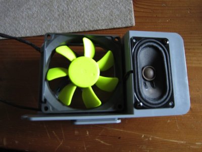
Wow, you did put alot of work into this.

I have also been looking into fan control for my G5 which has 6 (non-PWM fans) in the original locations, plus another PWM fan attached to the CPU heatsink, then there are two fans in the PSU. So all up 9 fans in total.

I was looking to control the 5 fans in the CPU bay all from the PWM signal from the motherboard, so I devised the following (simple) circuit to convert the PWM signal for use by the non-PWM fans.

540x405


It is simialr to yours, but you have used op-amps to drive the main transistor, where I used a simple transistor. Not sure what the the benefits of your approach as don't know much about op-amps. In my circut the first transistor acts as a driver for the main transistor which does draw some current.

I am not sure if this is helpful, but just my work so far. Haven't had time to implement this.
 
Please STFU !!!

Hi ...

Thanks for interest kiwisincebirth and minihack...
I know it was a lot of work, but it was fun and give back life to the original G5 fans,
I closed my G5 and when normal used I only hear the HDD spinning softly...

And Kiwi ... I can't see your picture so I don't know what you mean asking about the op-amps.
I tried whitout and then I didn't get enough power for the voltage controlled G5 fans (hungry for power too)
I used the op-amps to linear double the voltage.

You can easily upgrade this electronics for control more then 4 fans, and with the I2C sensors up to 8 sensors

PS If anyone want to use this for normal (positive) PWM controlling you can leave out the :
R1,R5-R7 resistor + C1-C4 capacitor
the quad op-amps
and can use a small transistor like 2n2222 or similar instead of the TIP120
 
Please STFU !!!

Little UPDATE


Here is a little software update and added a few pictured 'how it ended' to it :


IMG_0353.jpgIMG_0351.jpgIMG_0355.jpg

HDD, PCI, CPU-rear sensor
The CPU-front sensor I attached closely to the CPU-cooler heat pipes.

IMG_0358.jpgIMG_0359.jpgIMG_0361.jpg
IMG_0362.jpgIMG_0365.jpg

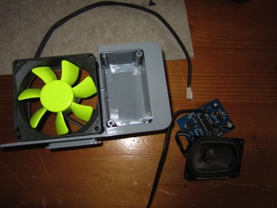
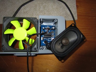
And as seen in the new software I made another pin setting called 'chime' (not yet finished)
for the startup apple sound ...

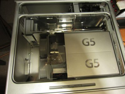
IMG_0302.jpgIMG_0303.jpgIMG_0305.jpg

(And later replaced that fan with back to the original fan)


Update for chime is followed up....
 

Attachments

  • OrgFanTest_r02.zip
    2.2 KB · Views: 168
Please STFU !!!

Hi ...

Thanks for interest kiwisincebirth and minihack...
I know it was a lot of work, but it was fun and give back life to the original G5 fans,
I closed my G5 and when normal used I only hear the HDD spinning softly...

And Kiwi ... I can't see your picture so I don't know what you mean asking about the op-amps.
I tried whitout and then I didn't get enough power for the voltage controlled G5 fans (hungry for power too)
I used the op-amps to linear double the voltage.

Here is another copy of the schematic, it is done in CircuitLab, so if you can open it you can actually run a simulation. Would appreciate any feedback.
 
Please STFU !!!

Hey kiwi,

Nice side btw, specially the simulate part...
Don't forget the protection diode if use that transistor, or it's gonna die in time
 
Kiwi's link brought me hear and what a find, awesome work sir. :thumbup: Cheers, Rossi.
 
....and a potentially simpler way for those more comfortable with mechanical modding than with electronics.
 

Attachments

  • Converting G5 fans.zip
    6.5 MB · Views: 219
Hi Rossi1959,
Thanks for the interest for my little project

And hi minihack,

I think both projects take a little bit work and time,
but the point is sharing some ideas and re-invent the wheel mac...

And yes ... your project looks good too ;)
And I'll give that a try ... just for the experience.

I even haven't think about to do something like you did,
but it looks good and my point using the original fans was (and you mention it at the video too)
that they transfer very much air
 
Status
Not open for further replies.
Back
Top