- Joined
- Nov 25, 2010
- Messages
- 1,211
- Motherboard
- AsRock X570M Pro4
- CPU
- Ryzen 3700x
- Graphics
- RX 580
Build Log 6 - LCD Display
This is by far the most challenging part of the entire project. Credit goes to the Dremel Junkie for his comprehensive tutorial at this link. This step in the project was perhaps one of the most difficult tasks I've ever completed with computer hardware. Getting the HDMI video signal from the NUC onto the G4 LCD was a tremendous challenge.
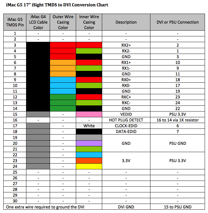
EDIT: More than 8 months after the completion of this build, I changed the wiring slightly as shown in the table below. I discovered in a later iMac G5 project that this 17" LCD requires 3.3V to the VEDID wire (as per the mfr spec), not 5V as is supplied from the DVI. It was a tedious task to repair, but may save long-term damage from over-volting pin 15 of the TMDS. The good part is, it is actually easier to wire the LCD this way, as opposed to the "Y" method used previously. Essentially the changes are as follows:
1. Connect Pink wire from grey LCD cable direct to 3.3V from the PicoPSU.
2. Connect DVI pin 14 and DVI pin 16 via 1KOhm resistor.
(Note that the iMac G4 and iMac G5 17" models are wired identically)
There are two video cables that come down into the G4 dome from the screen; the inverter cable for backlight and the LCD cable for video signal. Both require connections to either a DVI connector and/or a power source, in this case being the PicoPSU. I highly recommend reading through the Dremel Junkie's website for a complete and comprehensive tutorial on this subject BEFORE starting this step in a G4 iMac build.
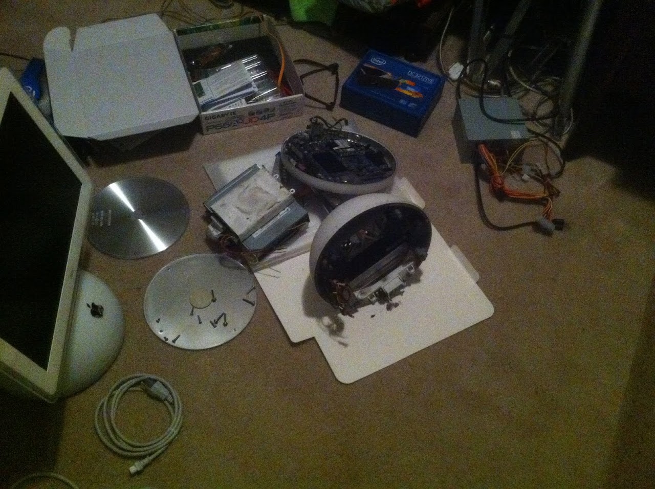
The first realization I made was that I needed several extra wires to connect the LCD. There was a method of shortcutting by splicing into existing LCD wires, but it was risky. These wires are hair-like strands that are extremely fragile. The only place to find the required wires was in a second G4 iMac. I decided I wasn't going to risk damaging my NUCiMac LCD cable, so I found a non-working G4 on Craigslist for dirt cheap. Another option is that iMac necks are readily available on eBay as well, but this was very convenient.
Stealing the LCD cable out of the second (non-working) G4.
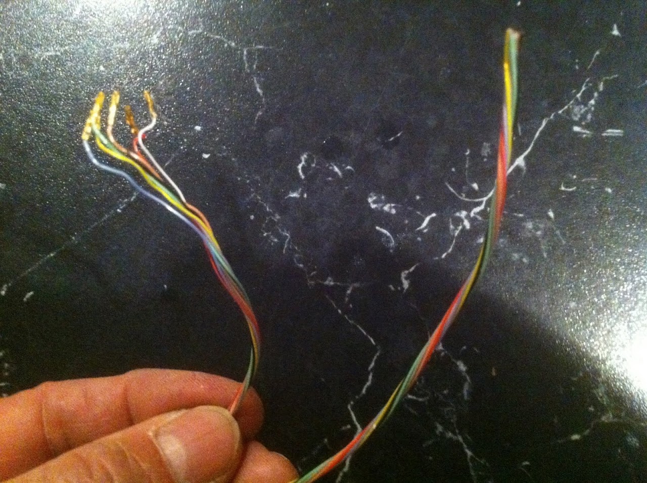
These are the extra wires I needed from the 2nd iMac
This is my existing NUCiMac LCD cable ready to connect. Disassembly only took a few minutes.

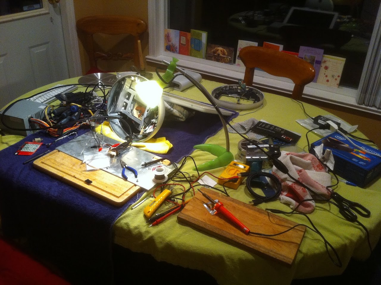
I set to work, following the Dremel Junkie's guide to the letter. I used my other NUC build (G4 Cube PSU) to test the connection via HDMI. Here's what the workstation (our kitchen table) looked like for the operation.
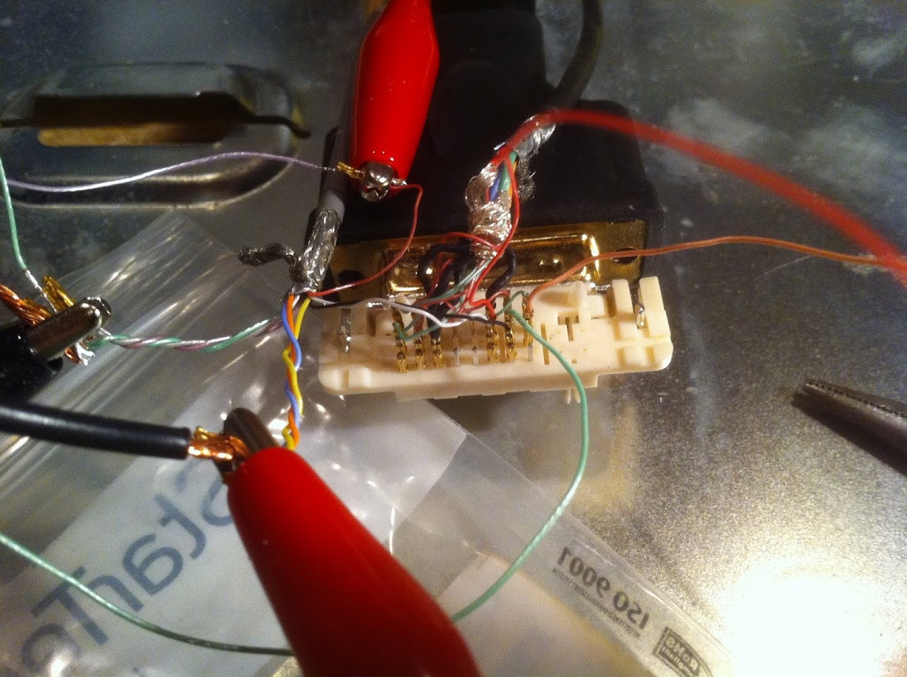
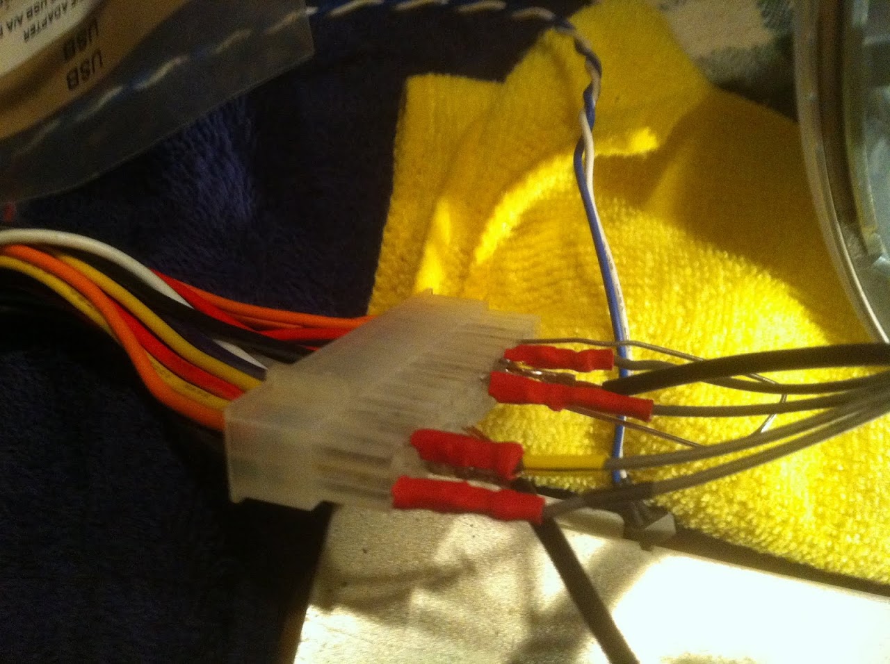
I constructed the new DVI connector wiring with alligator clips first to verify functionality. The DVI connector and HDMI adapter were secured down with heavy velcro so they would not move. These wires are VERY delicate. There are 17 in total to connect to the DVI, and two that are connected to the PSU.

Alligator clips would later be replaced with soldered connections after functionality was successful.
The PSU connections. This will be a PicoPSU when the build is done.
After a couple of mentally exhausting hours, I connected the HDMI from the Cube PSU machine and here's what happened

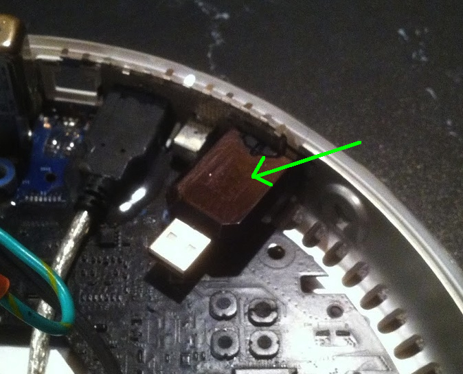
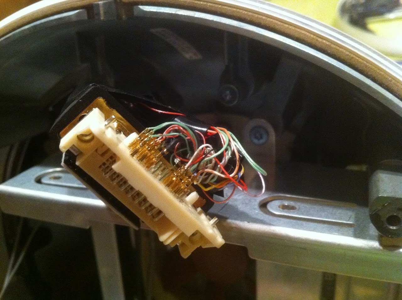
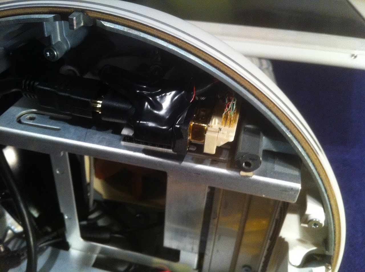
The final step was to solder, package and securely mount the final assembly in a location where is was safe from movement or damage.

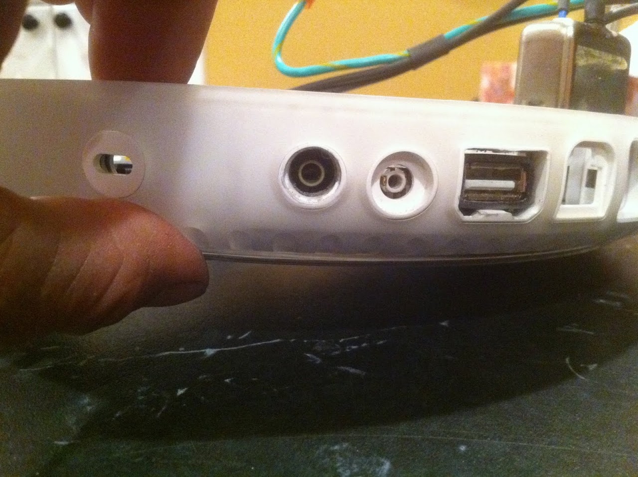
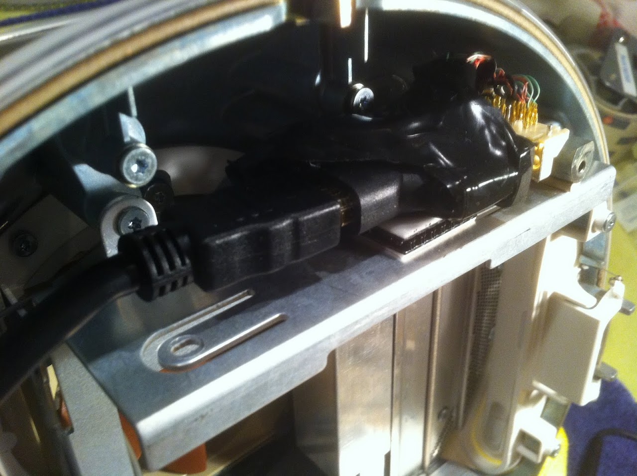
HDMI Cable attached. Mission Accomplished!
Ersterhernd
This is by far the most challenging part of the entire project. Credit goes to the Dremel Junkie for his comprehensive tutorial at this link. This step in the project was perhaps one of the most difficult tasks I've ever completed with computer hardware. Getting the HDMI video signal from the NUC onto the G4 LCD was a tremendous challenge.
EDIT: More than 8 months after the completion of this build, I changed the wiring slightly as shown in the table below. I discovered in a later iMac G5 project that this 17" LCD requires 3.3V to the VEDID wire (as per the mfr spec), not 5V as is supplied from the DVI. It was a tedious task to repair, but may save long-term damage from over-volting pin 15 of the TMDS. The good part is, it is actually easier to wire the LCD this way, as opposed to the "Y" method used previously. Essentially the changes are as follows:
1. Connect Pink wire from grey LCD cable direct to 3.3V from the PicoPSU.
2. Connect DVI pin 14 and DVI pin 16 via 1KOhm resistor.
(Note that the iMac G4 and iMac G5 17" models are wired identically)
There are two video cables that come down into the G4 dome from the screen; the inverter cable for backlight and the LCD cable for video signal. Both require connections to either a DVI connector and/or a power source, in this case being the PicoPSU. I highly recommend reading through the Dremel Junkie's website for a complete and comprehensive tutorial on this subject BEFORE starting this step in a G4 iMac build.
The first realization I made was that I needed several extra wires to connect the LCD. There was a method of shortcutting by splicing into existing LCD wires, but it was risky. These wires are hair-like strands that are extremely fragile. The only place to find the required wires was in a second G4 iMac. I decided I wasn't going to risk damaging my NUCiMac LCD cable, so I found a non-working G4 on Craigslist for dirt cheap. Another option is that iMac necks are readily available on eBay as well, but this was very convenient.
Stealing the LCD cable out of the second (non-working) G4.
These are the extra wires I needed from the 2nd iMac
This is my existing NUCiMac LCD cable ready to connect. Disassembly only took a few minutes.
I set to work, following the Dremel Junkie's guide to the letter. I used my other NUC build (G4 Cube PSU) to test the connection via HDMI. Here's what the workstation (our kitchen table) looked like for the operation.
I constructed the new DVI connector wiring with alligator clips first to verify functionality. The DVI connector and HDMI adapter were secured down with heavy velcro so they would not move. These wires are VERY delicate. There are 17 in total to connect to the DVI, and two that are connected to the PSU.
Alligator clips would later be replaced with soldered connections after functionality was successful.
The PSU connections. This will be a PicoPSU when the build is done.
After a couple of mentally exhausting hours, I connected the HDMI from the Cube PSU machine and here's what happened
The final step was to solder, package and securely mount the final assembly in a location where is was safe from movement or damage.
HDMI Cable attached. Mission Accomplished!
Ersterhernd
")