Contribute
Register

Ersterhernds iMac G5 (iSight 20 A1145) Project

Status
Not open for further replies.
My TMDS iMacs are all working like a dream after nearly 2 years of daily use. I cannot see any personal reason to pursue tackling an LVDS iMac when many TMDS units regularly appear for sale. That said, I'd sure be interested to see somebody else find success with one.

Cheers!
 
My TMDS iMacs are all working like a dream after nearly 2 years of daily use. I cannot see any personal reason to pursue tackling an LVDS iMac when many TMDS units regularly appear for sale. That said, I'd sure be interested to see somebody else find success with one.

Cheers!


Hi Ersterhernd
I have been following your G5 iMac builds with great interest and in particular your iSight G5 iMac build, your attention to detail is amazing. I recently obtained both a G5 iMac and a G5 iSight iMac for £15.00 off Gumtree, the G5 Imac had a cracked case and no PSU but the G5 iSight case was perfect after and good clean. The iSight iMac screen was damaged so after swapping the screens (both were LG LM201W01) and a new PSU mains input bridge rectifier and 4A fuse…


IMG_0472.JPG


…the iMac G5 iSight was up and running. I wanted to fully test the display, and fans etc were all working before stripping…

IMG_0479.JPG


I have progressed an little and are at the point of installing the INTEL NUC DC3217BY…

IMG_0492.JPG


I plan to retain the DVD ROM burner, inverter and the now repaired PSU, the PSU looks good with no bulging caps or burnt components…

IMG_0468.JPG


In your iSight build you retain a large portion of the logic board (on the right) whereas I plan to dremel most of this board away and only retain the I/O portion of this board, is this O.K?. I would like to keep as much of the functionality of the iMac as possible so would like to keep the Ethernet, mic input, headphone output and 3 x USB 2.0. ports. The NUC requires 19V DC which I can supply via a 12v to 19v upverter…


Screen_Shot.png


Any advice and encouragement would be most welcomed.
 

Attachments

  • IMG_0472.JPG
    IMG_0472.JPG
    2.8 MB · Views: 331
Hi colingmo,

Its great to see another iMac project beginning after a long period of the 'doldrums' on this forum. The iSight 20" is a real challenge because it is VERY shallow in depth, but makes a terrific mod, ours is still used every day nearly 3 years after completion. It uses the same Intel NUC as you've selected.

A few pointers for you as you commence...

1. Measure the Depth of your mod continuously as you work to make sure it closes. This is extremely important.

2. You will need to keep 2 cutouts of the Apple Logic board to achieve:
a) Native I/O on the rear (NOTE: I could NOT get the iMac ethernet port to work)
b) The iMac power button and LED.

3. There are 2 variants of the upconverter you pictured, get the SMALL one, not the one above.

4. You will have a challenge turning the native PSU on and off. A couple of years ago I spent considerable time figuring out how to do it. Have a careful read of this post before you get much farther. I have only seen a single PSU used in concert with a micro-controller to handle the on/off function. To date, I have not seen the linked method used successfully, albeit I believe it is entirely possible if implemented correctly.

5. Take your time with each and every step, especially when testing power, as its easy to burn parts with a simple error. Enjoy the entire project regardless of the hurdles you will face.


Also, start your own thread so we can all follow your progress. Good Luck!


Cheers!

Ersterhernd


Thanks Ersterhernd for the advice and your pointers. Your correct, you need to be millimeter perfect to get everything to fit into the case. It's looking like your power arrangment using the existing PSU and inverter at this link is worth testing on my 20" iMac, I'll let you know how I get on, also your 14pin motherboard plug assignments detailed in the link are spot on. I plan to dig a little deeper into using the ethernet and audio sockets, time will tell if I can get them to work. Didn't know there were two sizes of upverter, thank's for the advice, back to work!
 
Hi colingmo,

Its great to see another iMac project beginning after a long period of the 'doldrums' on this forum. The iSight 20" is a real challenge because it is VERY shallow in depth, but makes a terrific mod, ours is still used every day nearly 3 years after completion. It uses the same Intel NUC as you've selected.

A few pointers for you as you commence...

1. Measure the Depth of your mod continuously as you work to make sure it closes. This is extremely important.

2. You will need to keep 2 cutouts of the Apple Logic board to achieve:
a) Native I/O on the rear (NOTE: I could NOT get the iMac ethernet port to work)
b) The iMac power button and LED.

3. There are 2 variants of the upconverter you pictured, get the SMALL one, not the one above.

4. You will have a challenge turning the native PSU on and off. A couple of years ago I spent considerable time figuring out how to do it. Have a careful read of this post before you get much farther. I have only seen a single PSU used in concert with a micro-controller to handle the on/off function. To date, I have not seen the linked method used successfully, albeit I believe it is entirely possible if implemented correctly.

5. Take your time with each and every step, especially when testing power, as its easy to burn parts with a simple error. Enjoy the entire project regardless of the hurdles you will face.


Also, start your own thread so we can all follow your progress. Good Luck!


Cheers!

Ersterhernd


Thanks again for the advice, I have started my own thread, comments and advice appreciated.
 
Hi ersterhernd,

This is very impressive and very nice mod!!

I'm now modding Imac G5 20in (A1076)
Using Thin m-itx with desktop i3 CPU.
Everything went very smooth so far based on information from you and all other frontiers.

But after read all your post, now I became more greedy.
Now I'm looking into A1145 mod instead of A1076 to get iSight camera.
And also looking for higher resolution as G5 iMac's 1680x1050 is only a downside from my point of view.

So here's my 2 questions for A1145 mod:
1. How much room do I have? What mm do I have from LCD backplate to the silver foil surface?
2. Have you ever looked for higher resolution LCD that can fit with the frame? I know even though there is, modding it would be nightmare but I'm curious if there's an option. Looking for at least FHD LCD

Thanks!
 
Hi ersterhernd,
So here's my 2 questions for A1145 mod:
1. How much room do I have? What mm do I have from LCD backplate to the silver foil surface?
2. Have you ever looked for higher resolution LCD that can fit with the frame? I know even though there is, modding it would be nightmare but I'm curious if there's an option. Looking for at least FHD LCD

Thanks!

Hi nudoli,

The A1145 has significantly less interior space than the A1076, due to the tapered design towards the outer edges. The A1145 is also harder to work on if you need to get back inside, because you have to remove the front bezel and screen to get at the internals. I modded two iSight iMacs (17" and 20") and three non-iSight A1076's. With the exception of the iSight camera, the A1076's are a far superior shell to work with, and repair later.

The deepest part of the A1145 was around 27mm if I recall, but don't quote me on that. Again, like I said, you lose depth as you move outward toward the edges.

As far as replacement high resolution panels, I've never been interested. The warmth and look of the old vintage iMac LCD's is one of the primary reasons these units are such a conversation piece when completed. Just my opinion of course.

Good Luck as you continue.


Ersterhernd
 
Build Log 9 - Video Installation (Part 2)

Part 2 of the Video Installation will detail the LCD and Inverter Wiring for the LG-Phillips LM201W01-STB2 panel found in the 20" iMac G5 iSight.


Parts Required

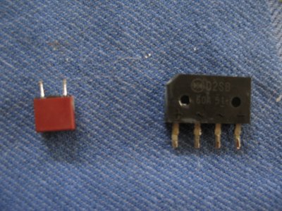
1. MOLEX PN 74320-4004 from Digikey.ca
2. Startech HDMIDVIFM adapter from Amazon.ca
3. 1K Ohm resistor (0.5W)
4. EMI shielding foil from the iMac G5 front bezel
5. LCD Cables and Inverter Cable from iMac G4 20"
6. iMac G4 20" Inverter part number 922-6129


The Pinouts


- Inverter Pinout -

srxw.png


vlja.png


- LCD Pinout -

rbnl.png


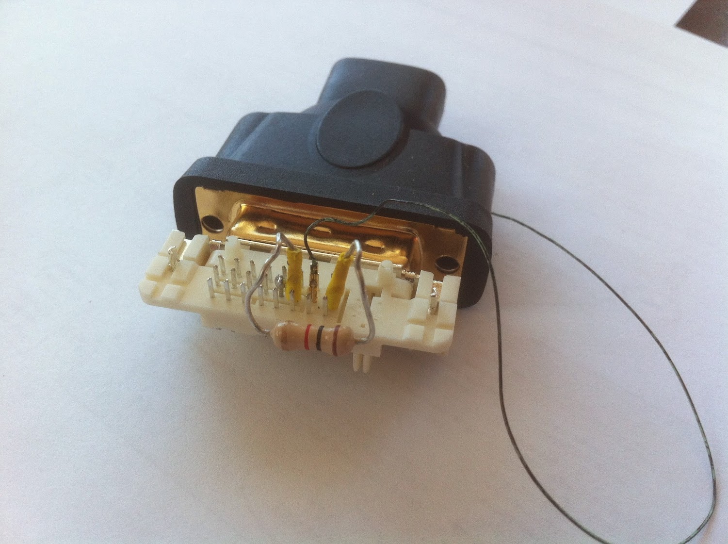
To Complete the DVI connection as noted in the above Chart, I used this method of soldering the 1KOhm resistor directly to the DVI pins 14 and 16. I used an extra iMac G4 wire for pin 15, although it would have been just as effective to solder a small wire directly to the pin, so no additional pinned wire would be required. I did this work prior to connecting any of the other pins. To obtain a VEDID signal, I soldered TMDS 15 (hot pink wire) directly to 3.3V from the PicoPSU.

This turned out to be a simpler solution than rewiring the Vedid/Hot Plug Detect loop into the TMDS.


IMG_5028.JPG


This is the completed work. Unfortunately DVI pin 1 (bottom left of the photo) needed to be soldered because the iMac pin got damaged somehow, as these tiny pins are very fragile. The heavy black wire on the right is a bridge between the DVI ground (as shown below) and the iMac LCD Cable shield (shown in second photo).

IMG_0054.JPG


9vt9.png


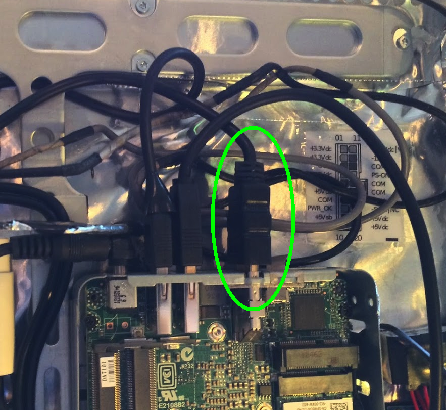
Final product after wrapping the assembly in EMI shielding foil (taken from the G5) and connecting it to an 18" HDMI cable (plugged into the Intel NUC). The height (depth) still allows sufficient clearance to fit the LCD panel on top of it all.

Connected to the assembly are 5 wires -

1. Black LCD cable
2. Gray LCD cable
3. Black GND wire
4. Yellow 12V wire
5. Orange 3.3V (VEDID) wire


IMG_0063.JPG


HDMI cable plugged into the Intel NUC

et6k.png


Ersterhernd

Thanks for such a great post. I've been working on a similar project, adapting a 20" iMac G5 iSIght to be used as an external HDMI monitor. But my information about the pinout differs from yours, which is interesting. When I peel back the protective shield around the connector opposite the 30-pin connector, it tells me that the VCC_Display voltages, which you have at 12V, are actually 3.3V. But clearly the 12V you used works.

Any thoughts on this? I'll attach a picture of the connector.

small_connector_1.jpg
 
Status
Not open for further replies.
Back
Top