Contribute
Register

Ersterhernd's G5 PowerMac Case Mod

Status
Not open for further replies.
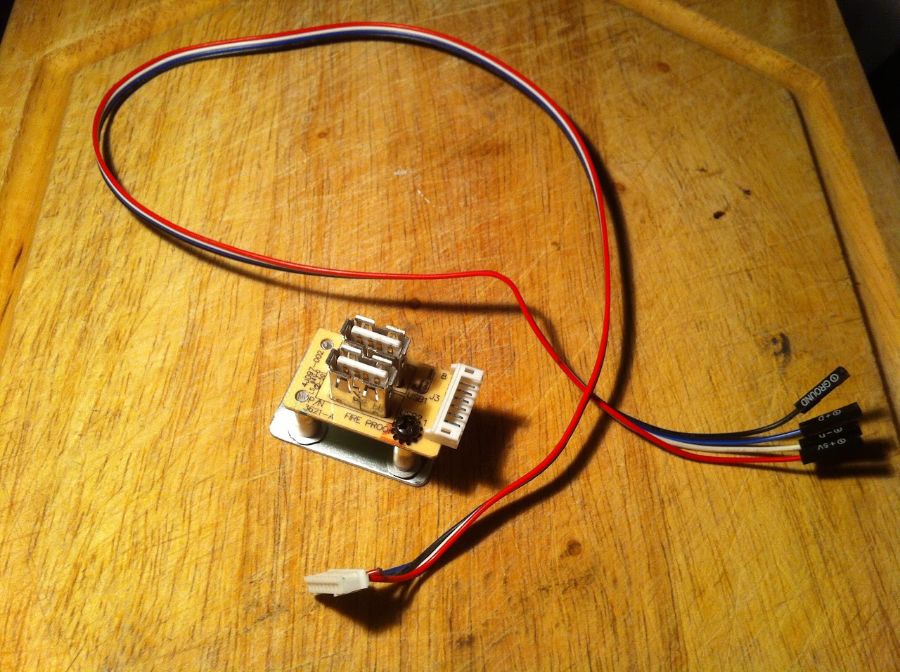
Step 7 -- Front Panel Power Connector

I hate wiring. Always have.

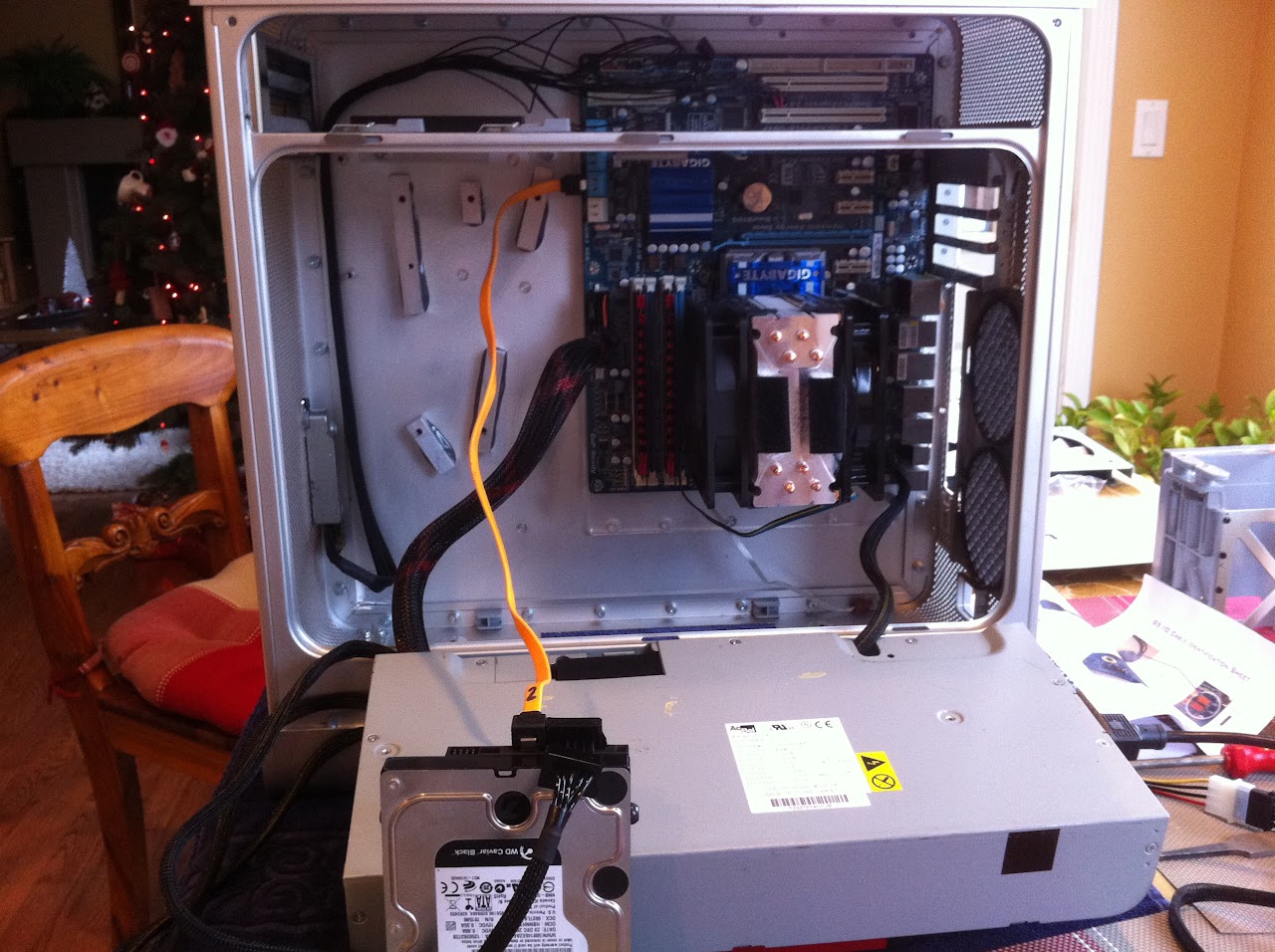
I have to admit that one of the true gems I found during working on this project was a fellow on the InsanelyMac forum known as AlohaCab. He constructs the entire required power wire for the G5 ATX mod, complete from the 18 pin connector at the head to all the required connectors for the motherboard. He wraps it in a beautiful mesh casing and includes all instructions. Take it out of the shipping box, read the connection instructions and plug it in. THAT'S IT.

All this for only 35 bucks plus shipping? YES.

Search for him and contact him directly on InsanelyMac. Best dollar you'll spend on this whole build, bar none.


IMAGE_00D3E7AC-723F-4A26-89DE-12070BC3F51F.JPG


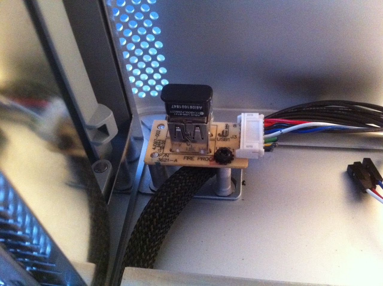
Testing the Front Panel Power. The system booted to OSX straight away with full front panel functionality. Love it.

IMAGE_B5BCF83A-48E9-4C00-8552-E9A8FA418441.JPG


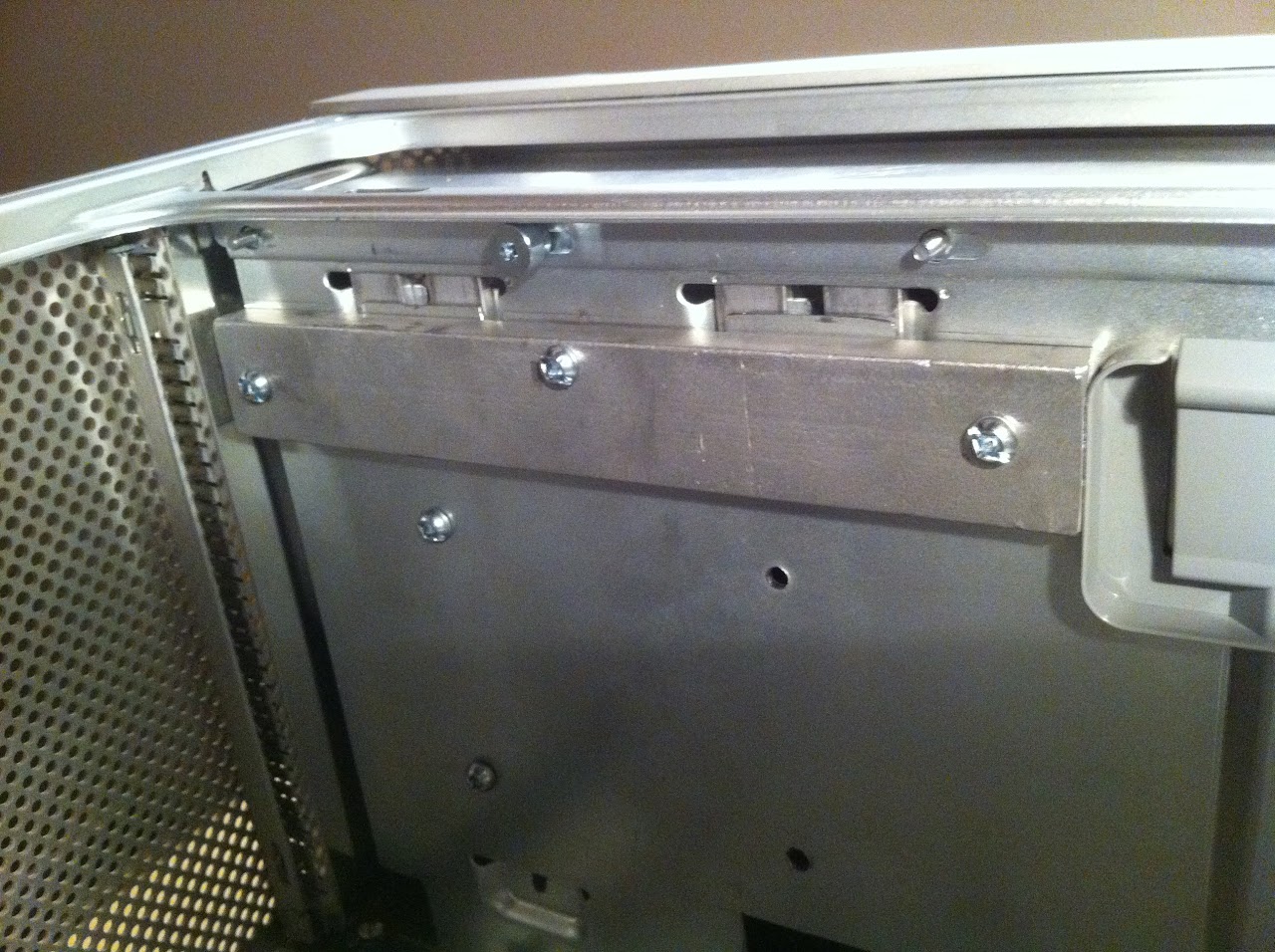
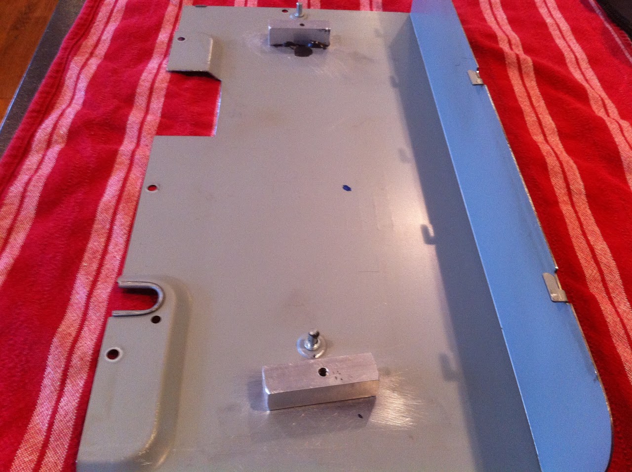
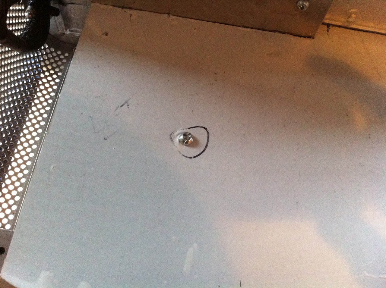
I JB Welded one of the previously removed G5 standoffs down in the front corner and zip-tied the power cable to it.
This eliminated any stress on the 18-pin connector so it will never come loose.

IMAGE_9823B6C2-7334-4BFD-88C7-1FE0B3E6E798.JPG
 
Step 8 -- Front Cooling Fans

I had perhaps my biggest surprise of the project when I completed the installation of the 2x140mm front fans. I knew that the assembly required solid functionality along with aesthetically pleasing looks, because its right in the front of the case.

After some research, I ordered this fan rack from Lian Li. Its the T60-1A.
I got it from here -----> http://www.performance-pcs.com/catalog/index.php?main_page=product_info&products_id=28993

screenshot_41.jpg


The fan bracket is mounted to the top left existing G5 standoff and a bottom foot that I made for the diagonally opposite corner.

Handy Hint: If you don't have any G5 motherboard standoff screws, the thread of the G5 standoffs matches the UK Electrical Socket Screws M3.5 just get a bunch of them 2" long and cut them off to length as you need them. Very handy to have and cheap, get them on Amazon or eBay. See pic below.

screenshot_42.jpg


Lian Li T60-1A mounted to the top left standoff and bottom right mounting foot

IMAGE_62EA1761-53CD-4D7E-9BDB-B11CF8DFB77D.JPG


I threaded the aluminum foot and used a bolt to secure the fan rack to it. (No bolt here yet)

IMAGE_9CAD2110-66D3-4BC0-B836-CB6FDE4E224F.JPG


Here's the front view of the fans and Lian Li Rack. I thought it turned out great, and its as solid as a rock in there.

IMG_7476.JPG
 
Step 9 -- HDD Activity LED

This mod may not be for all, but I like to know whats happening with my hard drives by way of the HDD LED. The G5 front panel only has the power indicator LED, so I took it upon myself to add my own. I ripped a red one out of an old case I had in the closet and installed it with JB Weld so the tip of the LED was stuck into the first hole vertically above the white G5 power LED.

IMAGE_A6AC7084-39B0-4A7E-AE24-36E6444CD19F.JPG


It can't really be seen when its not lit up, but its in there directly above the G5 LED.
The hole looks black in this lousy picture of it.

IMAGE_F2825679-618F-4CC0-83AD-27FE28489EE4.JPG


To see the HDD LED in operation have a look at this video...
https://www.youtube.com/watch?v=Rc-3C2WxXZg
 
Step 10 -- Built-in Bluetooth

With only a single USB port on the front panel, it was apparent that my Asus BT-21 bluetooth (which works flawlessly with OSX) was going to need a new home. Not wanting to have to stick it into one of the rear USB ports on the back I/O panel, I decided to try and fabricate a suitable workaround.

First, I hacksawed into the front cover panel of an old case I had in the closet. I pulled the front USB connector circuit board out of it and mounted it with JB Weld to 3 motherboard standoffs that I had torn off the G5. Btw, KEEP all the standoffs. DON'T throw them out, you may need them!


USB panel mounted to standoffs with a G5 motherboard screw and a fabricated backplate

IMAGE_0147E7C3-2AAA-4754-B855-DD74D6E65382.JPG


IMAGE_A00DE228-C165-436A-89A0-1A8B505CE950.JPG


As line of sight is very important for consistent bluetooth connectivity, I JB Welded the assembly to the top corner of the case above the DVD door (I'm not installing a DVD drive in this machine, as I consider it a waste of precious space internally when a USB DVD can be used instead). With the placement in this location, my Apple Magic Trackpad is less than 12" from the ASUS BT-21, as the computer is underneath the right side of my desk where my Trackpad sits. To test out a different location, I moved the G5 up on top of the desk to the left of the screen, and BT function was sketchy. Must be the aluminum case or something, my point is that to run the BT internally, it apparently needs good line of sight with its devices.


Bluetooth board mounted into G5 with Asus BT-21 inserted. The bluetooth works flawlessly now that the system is finished.

IMAGE_D50FB6AF-BDDC-456A-A030-2CEE2F50E0EA.JPG


Edit: There is an update to the Bluetooth in post # 20 below.
 
Step 11 - Top Tray Cover Door Mount and CPU Cover Mount


In order to give the system the finished appearance and Apple branding, I did two final steps to finish the G5 Case off aesthetically.

1. I installed a matching 1/16th aluminum cover with an iPhone Apple sticker onto the top tray
2. I installed a G5 CPU cover onto my CoolerMaster cooler.

IMG_7500.JPG


For the Top Tray Cover I removed the 2 grey plastic locking levers from the DVD mount in the top tray. I drilled the tray from the bottom and JB Welded three threaded standoff blocks around the DVD mounts as shown in this pic. They are visible directly in front of my 2.5" HDD rack on the top tray, and line up perfectly with the three drilled holes in both the tray and the mounting bar discussed below. As I've said before, make sure everything is bolted together tightly when the JB Weld is applied and allow to cure. Once the JB is hard, undo the assembly bolts. This is the only way the holes in each piece of the assembly will properly align.

IMAGE_83AC6AB3-8687-4A01-A2C6-E2D958AD0B83.JPG


I then made a mounting system with a bar that locks the door in place into the 2 DVD mounts. The three pics below show how it was done. It took a lot of careful measurement, and I tested it all out for fitment with clear tape before using the JB Weld. In the first pic you can see that I've JB Welded two small thin pieces to the top surface of the mounting bar. These were cut from the excess that I cut off the G5 top tray. They were required to accomodate a minor bit of extra thickness needed for proper securing of the prongs up into the raised DVD mounts. The mounting bar was cut from a piece of 3/8" x 1" aluminum stock that I had in hand, but any sized piece could be used, as it mounts to the bottom of the tray with bolts. The four prongs shown were bent identically from 1/8" x 1/2" aluminum flatbar.

IMAGE_6ADF10D4-280C-46F3-A4F0-A9AF44927744.JPG


IMAGE_DD387752-C2C6-4BF7-9BFE-C76E10039C61.JPG


IMAGE_1E03CB72-1676-4200-927D-A1F79299FD2E.JPG


The bottom mounting bar screws into the standoffs to tightly secure the tray cover door. You cannot move it at all. It worked great. The four mounting prongs can be seen inserted into the DVD mounts and tightly squeezed into position with the bottom bar.

IMAGE_E3D7D650-61FE-4B61-86DC-8E7931995F74.JPG


For the G5 CPU cover, I simply JB Welded two 1/2x1/2 pieces to the end of my CPU cooler and applied velcro to them and to the actual cover as well. It worked out that there is only 1/8" of clearance when I put the side cover back onto the case. Wow that was close!

IMAGE_F450BA5E-5FE6-4652-A576-D7A79D899591.JPG


The velcro can be seen here. The G5 cover is solid and doesn't move because its so light.

IMG_7496.JPG
 
Step 12 -- The Case Floor


The final step in this work log.

I actually purchased the genuine Apple G5 PSU Cover off eBay to use as the floor of the project, but when it arrived and I test fitted it, it simply did not give me the look that I wanted to finish the work off properly. The reason I bought it in the first place was because it had 2 pre-drilled holes that mated up to the G5 PSU perfectly for securing it down onto the PSU. Unfortunately though, it looked like hell when I put it in, so out it came.

I bought a 7-1/2" by 16" piece of 1/16" aluminum plating to match the material used in the Cable Management Cover Plate (See the first pic of Step 5 -- Cable Management Cover Plate and G5 Hard Drive Cage Mounts) for a consistent look. The piece still had the protective peeling on it which I didn't remove until after the project was completed.

HINT: The floor required a lot of dremel cutting. For 100% perfect cuts of the floor plate, purchase a second piece of aluminum plating with at least one clean machined edge. When cutting, use the 2nd piece as a guide with it clamped directly onto the top of your floor piece. Have your finished surface facing down and clamped underneath your 2nd piece so you are cutting away the excess while rubbing the dremel cutting wheel along the straight edge of the 2nd piece. When I finished cutting and filing, I could not tell the difference between the cut edges of my floor piece and the machined edges, it was that good!


The cut (still unbolted) floor piece

IMAGE_C6227212-7781-4334-B895-C84B5E5653EF.JPG


The measurements

IMAGE_0F6CE36B-FED1-4D4D-8AF9-5846C0A2C5A5.JPG


Drilling the two mount holes accurately to secure the floor to the G5 PSU Shell was absolutely critical to the proper seating of the case floor piece. To accomplish this, I followed these steps...

1. Selected and marked two drill locations on the floor piece
2. Removed floor piece from case
3. Removed G5 PSU from case
4. Gutted all contents of the G5 PSU
5. Tightened Lid back onto empty G5 PSU
6. Reinstalled empty G5 PSU shell into case with four bottom screws tightened
7. Drilled tiny pilot holes into floor piece
8. Reinstalled floor piece into case on top of G5 PSU
9. Tightly clamped the floor piece into final position with 2 Irwin Clamps
10. From INSIDE THE CASE drilled out the pilot holes and G5 PSU shell lid with one motion
11. Unclamped and removed floor piece and G5 PSU shell

This process left 2 perfectly aligned holes in the floor piece and G5 PSU shell lid. The drilling MUST BE DONE INSIDE THE CASE with the FLOOR CLAMPED to the tightly mounted G5 PSU. Fortunately my drill just barely fit.


For the final step, I bolted and JB Welded two threaded standoff mounting bars to the inside of the G5 PSU lid so the floor piece could be properly tightened down. The standoff mounting bars are shown in the pics below. Once again, bolt everything together with the JB weld applied, let it harden for 24 hours, then undo it all.

IMAGE_88A123D8-C923-406F-B4DC-666CC516B944.JPG


IMAGE_ECB4E297-D76A-4554-8A43-954DACD6BEB5.JPG


Everything remounted into case and secured with 2 bolts

IMAGE_49970F07-8FF6-4088-9003-AD44C786C492.JPG


Protective peeling off and the finished product gave the exact appearance I wanted
(The short vertical aluminum plate between the motherboard and floor plate is simply velcroed into position)

IMG_7494.JPG


I hope readers of this work log find it informative. I'd be happy to answer any questions.

For my complete photo album of the build go here -----> https://picasaweb.google.com/100949536429216905468/PowerMacG5Project


Regards,

Ersterhernd
 
Wow.

This is a super detailed log. Thanks very much for taking the time to post it - some really brilliant and novel solutions to the G5 case challenges.
 
Thank you for posting your log and all of the photos. I like your re-engineering solutions.

neil
 
Thx so much for the positive feedback.

I've added one more modification since this log was posted. The Bluetooth setup was too directionally sensitive for my liking. Although it works terrific with the G5 placed almost directly under the trackpad that sits on the desktop, I wanted the freedom to move the case later if I so desired, without any risk of compromising BT functionality.

I decided to build up (on an empty PCI-E 1x card) a Genuine Apple A1181 BT module with 3.3v supplied to it. The antenna actually sticks out the top PCI slot at the rear about 1 inch, so is not really visible. The setup works tremendously. I can carry my Magic Trackpad all the way across the room in any direction and still get precise crisp cursor control.

I followed the instructions in the PDF available here...

http://www.insanelymac.com/forum/to...ng-apple-bluetooth-module-in-your-hackintosh/


I highly recommend to anyone using Bluetooth devices to try this mod. Off eBay, the parts totaled under twenty dollars shipped. In my opinion, for authentic Apple hardware this is well worth it.

Apple Infrared is on the way. Will keep the progress posted here.

Regards,
Ersterhernd
 
Status
Not open for further replies.
Back
Top