- Joined
- May 27, 2010
- Messages
- 2,364
- Motherboard
- Dell Optiplex 9030 All in One
- CPU
- i5-4690K
- Graphics
- HD 4600
- Mac
- Classic Mac
- Mobile Phone
By popular request - guide to using the Cube Switch.
Some time ago I did my first mod putting a Mac Mini into a Cube casing. I had a few Cubes I had been repairing and selling on and had a stock of spare parts and thought it’d be good to use a Cube switch - as they are cool.
Others have found my write up on the web and used it and I realize it is probably better to add a few bits to the write up now and make it clearer as it is not just there to remind me how I did it, but needs to be understood by others!
Background Discussion
You can skip this bit if you wnt and just go to the "How To" further down. If you get stuck though come back to this as it may help you understand what you did wrong.
Starting off it is useful to mention here what my investigations with a multimeter into how the switch actually work found out.
The image below is one I took to explain how to hook up to a Mac Mini to control it. Hooking up to a PC switch is the same though:
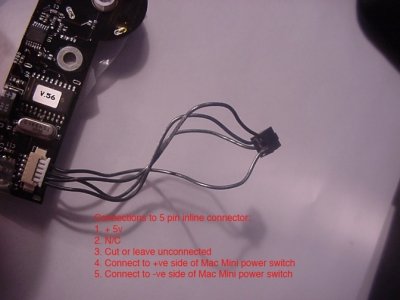
I have labelled the picture above with numbers working downwards from the connector wires of the white connector on the left of the photo. Looking at this connector there are five pins that I have numbered 1,2,3,4,5 working down from the top. The picture shows the connector as it is originally and NOT after conversion. The writing on the picture was my own notes at the time on what to do with the pins to make a working conversion.....
For the original Cube only pins 1, 3,4,5 (counting down from the top) are used. Pin 2 is not connected to anything at all on the board and is just there to make up the numbers.... Of the pins that are connected, this is what I saw when looking at the signals that a real Cube uses:
A. Pin 1 is ALWAYS connected to 5v as long as the machine is hooked up to a mains outet.
B. Pin 2 is not connected.
C. Pin 3 is referred to in other write ups as a “command line”. Basically it gets stuff from the Cube motherboard and I think it actually controls the LED of the Cube proximity switch to stay either “steady” or “pulsing”. If you cut this line to a real Cube then the LED stays off and the volts at that pin are around +5v. However, if you ground (momentarily) the wire then the LED glows strongly - regardless of whether the PC is on or off and this condition persists until the power is physically removed from the computer (unplugged at the mains!) - it glowed at full strength all the time.* Interestingly if you connect the line to ground a second time, then the LED goes off, but as soon as the line goes back to a floating condition again the LED comes back on again persistently. I thought that maybe this function could be used to work the LED function in a correct manner, but I couldn’t find any combination in which using this command line would give me what I needed. I suspect it needs some sort of extra external control circuit from the Mac Cube to make it work properly and merely using a pull-up resistor to 5v or pull down to zero volts is not adequate. While this is all interesting, it didn’t get me anywhere so in my mod I left this pin unconnected.
D. Pins 4 goes to the +ve (plus) side of the power switch connection to the mobo
E. Pin 5 goes to the negative side of the power switch connection to the mobo.
The switch works by connecting pins 4 and 5 together internally when a finger approaches the proximity sensor - i.e. these are the ones that actually turn the Cube on or off according to the proximity switch state.
How to use the switch
Before you do anything a two warnings.
1. In the pictures and description you'll see I have made solder connections directly to my PicoPSU. These connections MUST be made precisely and with a fine tip on your soldering iron. This is not a mod on which to make your first solder joints......the consequences of making a solder bridge (short circuit) between pins on the pico can mean a fried pico or could harm the mobo. If you are using an extender cable on your picopsu I recommend tapping into the wires of the extender instead of directly to the board.
2. While the switch has no visible earth connection, it does still need one. The switch takes it’s ground from the two screws that hold it to the Cube front plate. So when testing this switch you need to either be using it connected to your computer case and that case needs to be earthed so that the switch picks up the ground from the case OR give the switch it’s own local earth by connecting an earth wire (e.g. black from a molex plug) directly to one of the mounting screws. Failing to provide an adequate earth means it’ll do some very funky stuff with shutdown and restart looping. Here is an example of how you could earth the switch:
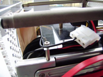
In that example I have just taken one of the black wires from a Molex plug and connected it to the metalwork of the case. This grounds the case and because the switch is also electrically connected to the case it grounds the switch too....I had to do this because where the power plug enters my case it is a plexi panel instead of the usual Cube metal one, so my case get's no natural earth/ground connection.
Here now is a wiring diagram I made up to show how the rest of the stuff needs to be connected:

You will also find this pinout diagram useful in an minute as it details what is what on an ATX power supply connector:
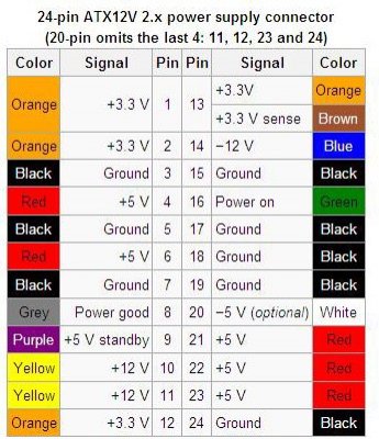
So taking all this info, and already having your earth connection, now give the Cube switch what it wants on pins 1,4 and 5 of it’s white connector.
Pin 1 of the white Cube connector MUST be connected to a permanently on 5v line. This is available from any ATX supply as shown in the pinout as pin 9. [Purple wire, +5v standby.] So tap into the purple lead and take it to pin 1 of the little white Cube switch connector. I am using a PicoPSU (which does not have the colours to help you) and I simply soldered the wire to the PCB of the Pico like this:
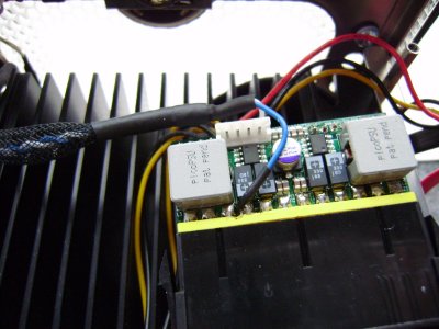
The photo is kind of deceptive, but the solder joint goes to the fourth tab in from the left hand side as shown on the picture - it looks like it is on the third but it's not - that's just the way the solder joint hardened.....but PLEASE take note of the warning about the consequences of messing up this solder connection.
Pin 4 of the white Cube conn. must be connected to the +ve side of the Power Switch output from the motherboard.
Pin 5 of the white Cube conn. must be connected to the -ve side of the Power Switch output from the motherboard.
Remember that this is not just a normal push switch and realize that it does matter if you hook up the Power Switch outputs from the mobo to the switch the wrong way around.
These three connections and the ground are all that is needed to get the proximity switch working.?
LED function.
Hooking up lines 1,4,5 as indicated above (and making sure the metal plate on which the switch sits is grounded) make the switch work absolutely fine, but the LED in that case will simply be illuminated when the switch has a proximity condition. In other words, it is lit only while the finger is nearby and otherwise is dark. If you want the LED to show the power condition of your computer too then you have to make the mod. shown in my wiring diagram by adding an extra connection.
First, here is the connection at the PicoPSU:
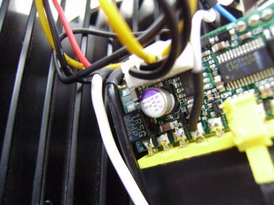
It's a simple wire soldered to pin 16 of the pico board.
That wire needs to be soldered to a 500 (or so) Ohm resistor (value not critical but between 400 and 600 is good) and then the other end of that resistor ends up here:
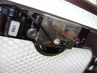
If you squint at my terrible photo you see it is soldered to the bottom leg (i.e. the one on the right!) of the LED.
( Here's the "science bit" as they say in the ad.s, please skip all this expalnation if you don't care why this mod works: LEDs are pretty simple and they basically glow when a current flows through them.
What I found is that the LED of the proximity switch functions by there always being a positive voltage on one side of it (the anode for techies!) and the negative side (cathode) is “floating” most of the time. Floating means not really connected to anything at all....
However, when a finger comes along and comes near to the switch to turn the PC on, for that brief moment the switch causes there to be a path to earth for the LED and so the LED lights up. When the finger goes away, the earth goes away and the LED cathode side floats again....so the light goes out.
Because of this behavior I figured that to get the LED to be on, we need to provide a path to earth for the cathode side of the LED whenever the PC is on, but remove it when it is off. It’d also be great if we could make it so that the LED glowed more strongly when a finger came close - for instance to trigger a sleep condition.
Thinking back to my old electronics I realized that by giving the LED a pathway to ground by using a suitable resistor that ran in parallel to the pathway that the switch PCB provides I could make the switch glow gently when the machine was on and then more strongly whenever the proximity switch was activated.
Looking back at the ATX pinout you can see that pin 16 of the ATX power supply spec is marked “Power ON”. That pin is actually a signal that comes from the motherboard and is at Ground volts (i.e. zero) whenever the PC is switched on, but is at high resistance or floating when the PC is off. Therefore Pin 16, light green wire, provides exactly what we want. However, we do not want to connect it directly to our cathode leg as we need to moderate the current to earth and not overload the LED.
So If you use a suitable resistor to connect this green line to the cathode wire of the proximity LED then it will light with a soft glow whenever the Cube is powered and a strong glow whenever the proximity condition is met. )
You can if you want just hook up a flying wire from pin 16 of your ATX supply to a resistor and solder the other end of the resistor straight to the LED cathode leg. That’ll work fine - no prob.s. YOU ARE DONE - stop here and congratulate yourself.
Beelzebozo kindly made a little video of the connections to the Pico to help out on this and here is a link to that:
[video=youtube;ZUTc_WuN0VM]http://www.youtube.com/watch?feature=player_embedded&v=ZUTc_WuN0VM[/video]
To avoid clutter I'll mention something else in the next post!!!
Good luck.
Some time ago I did my first mod putting a Mac Mini into a Cube casing. I had a few Cubes I had been repairing and selling on and had a stock of spare parts and thought it’d be good to use a Cube switch - as they are cool.

Others have found my write up on the web and used it and I realize it is probably better to add a few bits to the write up now and make it clearer as it is not just there to remind me how I did it, but needs to be understood by others!
Background Discussion
You can skip this bit if you wnt and just go to the "How To" further down. If you get stuck though come back to this as it may help you understand what you did wrong.
Starting off it is useful to mention here what my investigations with a multimeter into how the switch actually work found out.
The image below is one I took to explain how to hook up to a Mac Mini to control it. Hooking up to a PC switch is the same though:

I have labelled the picture above with numbers working downwards from the connector wires of the white connector on the left of the photo. Looking at this connector there are five pins that I have numbered 1,2,3,4,5 working down from the top. The picture shows the connector as it is originally and NOT after conversion. The writing on the picture was my own notes at the time on what to do with the pins to make a working conversion.....
For the original Cube only pins 1, 3,4,5 (counting down from the top) are used. Pin 2 is not connected to anything at all on the board and is just there to make up the numbers.... Of the pins that are connected, this is what I saw when looking at the signals that a real Cube uses:
A. Pin 1 is ALWAYS connected to 5v as long as the machine is hooked up to a mains outet.
B. Pin 2 is not connected.
C. Pin 3 is referred to in other write ups as a “command line”. Basically it gets stuff from the Cube motherboard and I think it actually controls the LED of the Cube proximity switch to stay either “steady” or “pulsing”. If you cut this line to a real Cube then the LED stays off and the volts at that pin are around +5v. However, if you ground (momentarily) the wire then the LED glows strongly - regardless of whether the PC is on or off and this condition persists until the power is physically removed from the computer (unplugged at the mains!) - it glowed at full strength all the time.* Interestingly if you connect the line to ground a second time, then the LED goes off, but as soon as the line goes back to a floating condition again the LED comes back on again persistently. I thought that maybe this function could be used to work the LED function in a correct manner, but I couldn’t find any combination in which using this command line would give me what I needed. I suspect it needs some sort of extra external control circuit from the Mac Cube to make it work properly and merely using a pull-up resistor to 5v or pull down to zero volts is not adequate. While this is all interesting, it didn’t get me anywhere so in my mod I left this pin unconnected.
D. Pins 4 goes to the +ve (plus) side of the power switch connection to the mobo
E. Pin 5 goes to the negative side of the power switch connection to the mobo.
The switch works by connecting pins 4 and 5 together internally when a finger approaches the proximity sensor - i.e. these are the ones that actually turn the Cube on or off according to the proximity switch state.
How to use the switch
Before you do anything a two warnings.
1. In the pictures and description you'll see I have made solder connections directly to my PicoPSU. These connections MUST be made precisely and with a fine tip on your soldering iron. This is not a mod on which to make your first solder joints......the consequences of making a solder bridge (short circuit) between pins on the pico can mean a fried pico or could harm the mobo. If you are using an extender cable on your picopsu I recommend tapping into the wires of the extender instead of directly to the board.
2. While the switch has no visible earth connection, it does still need one. The switch takes it’s ground from the two screws that hold it to the Cube front plate. So when testing this switch you need to either be using it connected to your computer case and that case needs to be earthed so that the switch picks up the ground from the case OR give the switch it’s own local earth by connecting an earth wire (e.g. black from a molex plug) directly to one of the mounting screws. Failing to provide an adequate earth means it’ll do some very funky stuff with shutdown and restart looping. Here is an example of how you could earth the switch:

In that example I have just taken one of the black wires from a Molex plug and connected it to the metalwork of the case. This grounds the case and because the switch is also electrically connected to the case it grounds the switch too....I had to do this because where the power plug enters my case it is a plexi panel instead of the usual Cube metal one, so my case get's no natural earth/ground connection.
Here now is a wiring diagram I made up to show how the rest of the stuff needs to be connected:

You will also find this pinout diagram useful in an minute as it details what is what on an ATX power supply connector:

So taking all this info, and already having your earth connection, now give the Cube switch what it wants on pins 1,4 and 5 of it’s white connector.
Pin 1 of the white Cube connector MUST be connected to a permanently on 5v line. This is available from any ATX supply as shown in the pinout as pin 9. [Purple wire, +5v standby.] So tap into the purple lead and take it to pin 1 of the little white Cube switch connector. I am using a PicoPSU (which does not have the colours to help you) and I simply soldered the wire to the PCB of the Pico like this:

The photo is kind of deceptive, but the solder joint goes to the fourth tab in from the left hand side as shown on the picture - it looks like it is on the third but it's not - that's just the way the solder joint hardened.....but PLEASE take note of the warning about the consequences of messing up this solder connection.
Pin 4 of the white Cube conn. must be connected to the +ve side of the Power Switch output from the motherboard.
Pin 5 of the white Cube conn. must be connected to the -ve side of the Power Switch output from the motherboard.
Remember that this is not just a normal push switch and realize that it does matter if you hook up the Power Switch outputs from the mobo to the switch the wrong way around.
These three connections and the ground are all that is needed to get the proximity switch working.?
LED function.
Hooking up lines 1,4,5 as indicated above (and making sure the metal plate on which the switch sits is grounded) make the switch work absolutely fine, but the LED in that case will simply be illuminated when the switch has a proximity condition. In other words, it is lit only while the finger is nearby and otherwise is dark. If you want the LED to show the power condition of your computer too then you have to make the mod. shown in my wiring diagram by adding an extra connection.
First, here is the connection at the PicoPSU:

It's a simple wire soldered to pin 16 of the pico board.
That wire needs to be soldered to a 500 (or so) Ohm resistor (value not critical but between 400 and 600 is good) and then the other end of that resistor ends up here:

If you squint at my terrible photo you see it is soldered to the bottom leg (i.e. the one on the right!) of the LED.
( Here's the "science bit" as they say in the ad.s, please skip all this expalnation if you don't care why this mod works: LEDs are pretty simple and they basically glow when a current flows through them.
What I found is that the LED of the proximity switch functions by there always being a positive voltage on one side of it (the anode for techies!) and the negative side (cathode) is “floating” most of the time. Floating means not really connected to anything at all....
However, when a finger comes along and comes near to the switch to turn the PC on, for that brief moment the switch causes there to be a path to earth for the LED and so the LED lights up. When the finger goes away, the earth goes away and the LED cathode side floats again....so the light goes out.
Because of this behavior I figured that to get the LED to be on, we need to provide a path to earth for the cathode side of the LED whenever the PC is on, but remove it when it is off. It’d also be great if we could make it so that the LED glowed more strongly when a finger came close - for instance to trigger a sleep condition.
Thinking back to my old electronics I realized that by giving the LED a pathway to ground by using a suitable resistor that ran in parallel to the pathway that the switch PCB provides I could make the switch glow gently when the machine was on and then more strongly whenever the proximity switch was activated.
Looking back at the ATX pinout you can see that pin 16 of the ATX power supply spec is marked “Power ON”. That pin is actually a signal that comes from the motherboard and is at Ground volts (i.e. zero) whenever the PC is switched on, but is at high resistance or floating when the PC is off. Therefore Pin 16, light green wire, provides exactly what we want. However, we do not want to connect it directly to our cathode leg as we need to moderate the current to earth and not overload the LED.
So If you use a suitable resistor to connect this green line to the cathode wire of the proximity LED then it will light with a soft glow whenever the Cube is powered and a strong glow whenever the proximity condition is met. )
You can if you want just hook up a flying wire from pin 16 of your ATX supply to a resistor and solder the other end of the resistor straight to the LED cathode leg. That’ll work fine - no prob.s. YOU ARE DONE - stop here and congratulate yourself.
Beelzebozo kindly made a little video of the connections to the Pico to help out on this and here is a link to that:
[video=youtube;ZUTc_WuN0VM]http://www.youtube.com/watch?feature=player_embedded&v=ZUTc_WuN0VM[/video]
To avoid clutter I'll mention something else in the next post!!!
Good luck.

