- Joined
- Mar 4, 2011
- Messages
- 32
- Motherboard
- Gigabyte P55M-UD2
- CPU
- i7
- Graphics
- GT 630
- Mac
- Mobile Phone
Last weekend I finished up on my second conversion of a Power Mac G5 Case to accept a mATX motherboard. By accident I got a hold of complete G5 “late 2005” on ebay for a bargain. In fact the unit was fully working, but compared to todays standards it was kind of slow, so with a little heartburn I took it down to the metal to start the work. This time I wanted to take it one more step to keep the looks inside as well as to the outside. (My other G5 case came as an empty shell, so I did not have quite as much options)
The main board (a Gigabyte H97) was already in service as Hackintosh system for a good year, in a decent, but not quite appropriate PC style case considering an almost all Apple household. So it was time to make it fit to an adequate case and here we go.
Here the core building blocks:


But first things first:
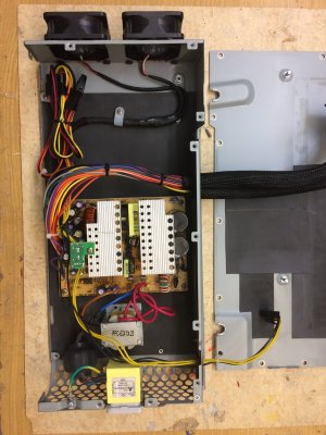
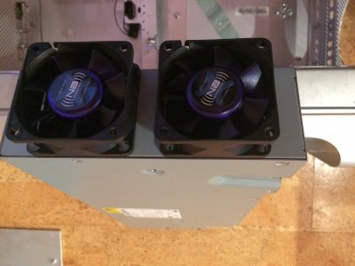
Converting the PSU was pretty much straight forward. Taking out the original power supply PCB, placing an ATX PCB on 4 short M3 standoffs, fixing the compensation inductor to the base, extending the power inlet wiring, a little shrink tubing, keeping the Apple noise filter in place and opening just a little space in the isolation rubber profile to feed out the ATX harness out of the case pointing straight up to where the ATX board has the connector. The 2005 model has solid copper bars feeding sideways to the motherboard, so that was kind of cool to use as a opening for the harness, no major metal work to be done. I replaced the original fans with NoiseBlocker 60 mm devices, which are providing enough airflow through the PSU case without nerve wrecking sound. The ATX supply was a no name 430W model with 120mm top blowing fan I had sitting on the shelve. This supply came with a whole bunch of cables for multiple disk drives, floppy drive, both SATA and IDE type of connectors but no cable management, so I was tempted to cut off all surplus wiring, by the end I did NOT and tugged them away in a corner of the pretty large Apple PSU box, just in case in need some for later.
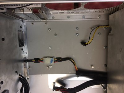
One of the 12V/5V drive cables I cut down and left just ONE Molex socket to be available. The drive supply cable of the Mac (for hard disk and DVD drive) happened to be long enough to be rerouted to half way under the mother board, so adding a mating Molex pin header, voila, there is power in the drive compartment completely invisible.
Step two, preparing the motherboard mount.
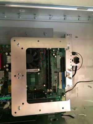
As stated before I did want to keep as much of the “infrastructure” to keep the looks. Fortunately a mATX board fits very nicely when lining up with the extension slots and the front part of the original processor / fan holding structure can stay in position. In this 2005 model the processor mount structure is DETACHABLE from the body, in a matter of minutes you can take out the little metal frame, cut off the “backwards facing” part (see picture). After removal of some 3 or 4 standoffs, which don´t fit the ATX locations anyway you have a roughly 280 by 190 mm flat open space. While I had been grinding them away with a Dremel last time I tried a different method this time: Take a robust tube, which fits tightly over the studs and break them off the plate with some gentle wiggling, the studs come off very easily!
By virtue of the the very low mounting studs, which had been holding the detachable processor support plate you have now “built in” mounting positions for your ATX motherboard tray. So a piece of 1mm sheetmetal of 280 by 190 mm essentially needed holes for ATX standoffs and some holes for the “original processor support plate” pattern, and here we go, a mATX board is in position, detachable, no Epoxy glue or alike.
Step three, the rear panel.
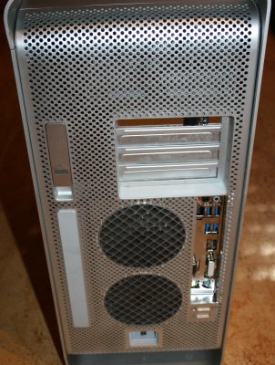
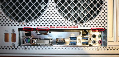
My original intent was to also keep the rear in original shape, I had seen some modifications, where folks have come up with patch wiring and have put sockets in the original locations for USB, Ethernet, Audio and so forth. I tried hard, but by the end I gave up: The clearance between the ATX connectors and the physical metal of the Mac case is about 15 mm or even less, so any type of patch wiring will stick out of the connector panel by some amount, while a socket mounted to the Apple back panel extends some good amount to the inside, so you have to be in a very lucky position, that the connectors and the sockets don´t collide in the little clearance you have available. I failed, because the Ethernet socket of my mother board, which I did not want to loose collided with BOTH available RJ 45 openings in the original rear panel of the Mac. So bad luck and I instead made minimalistic rectangular cut out of the back, put some aluminum framing around the gap and reach directly at the ATX board.
I left the orginal fan grill structure in it´s position to be able reuse all the inner air guide structure and fan mounts! The trade off is minimal, I am losing two audio sockets, one USB and the VGA output, which I can easily live with.
Step four, the front panel.
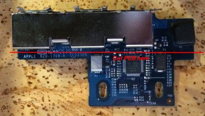
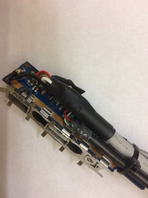
This model came with a front panel, which holds a little PCB extension, which is directly attached to the logic board, not the classic cable harness version. The general recommendation I found in the forum was: Buy the cable version, sell off the PCB version, position and mount is compatible, cable version is passive, wiring harness for ATX conversion is well documented. Checking ebay for offers was a bit disappointing, cause the “cable version”, mostly even WITHOUT the pigtail runs at a premium price these day, so I felt like: “May I need to take a closer look at what I have”. Making the long story short the PCB contains a firewire transceiver and a number of other active components, which would interfere with a passive patch wiring to the connector pads. So I decided to take my little Dremel tool and simply cut off the part of the PCB, which held the active components. Then I also cut through the very fine traces leading away from the solder joints of the connectors at the firewire socket, at the USB socket. With a multimeter I validated that none of the relevant pads had remaining contact to any of the surroundings. Blocking caps or tantal´s hooked up to the 5V USB supply line or the respective firewire power don´t hurt and can stay. In the same course of action I found three adjacent pads on the backside, which lead to the tiny power switch power LED three pin connector. Next step was to find a set of cables with appropriate motherboard ATX pin headers. A decommissioned PC USB, audio... front panel was a decent donor, so I soldered my harness directly to the front panel backside solder pads of the connectors: Audio, USB, Firewire plus 3 single wires for power, common and LED. A tie wrap by the end keeps the harness in place without stress to the delicate solder points of the wire tips. So far I have tested USB, Audio and the power button / power LED, all working out of the boot, except that I could not get the power LED to work properly with my H97M ATX board. (it worked fine with an old generation P4 ATX board, which I had used for the mechanical prep work!) I figured out that the trouble maker is the fact, that the Apple circuitry uses a common lead for the switch and the LED return. The H97M ATX board (and likely similar with other brands and models!) wants the switch going from ground to the input terminal while the power LED want the LED connected to the positive rail and the output of the motherboard is an “open collector” pulling to ground. So ideally a 4 wire connection would be best, well not an option here. I fixed this conflict with a “one PNP transistor /2 resistor “ inverter circuit in the LED path, so that a common ground return for both power switch and power LED works again. The little circuit is shrink wrapped to the post type header. See some illustrations below. Remaining test will be to try the firewire front connector.

Finishing touches:
The divider frame of the original Mac is obviously designed around the original motherboard, with the mATX board in place the memory slots and some other components do collide a bit. Also the mounting point close to the PCI/PCIe slot ports at the rear panel no longer lines up. So I had to trim the divider frame at the motherboard side to provide enough clearance and I added a little sheetmetal bracket at the far end to line up with new ATX mount point. By adding a few washers to simulate the thickness of the motherboard the divider frame now sits exactly where it was in the first first place. The rear fan plastic frame collides with the the “connector towers” (USB, VGA, Audio and Network), but a healthy cut out of the bottom of the frame helps it. The frame snaps back in place being held by 3 out of 4 legs and on the inside there is even enough clearance to mount fans.
I decided to leave additional fans as option for the future, I also left this intake side without any fans for now. Instead I am using a giant beQuiet cooling tower with a single 120 mm fan and expect it will give me enough flow through the tunnel, considering both ports being completely open. I´ll do some temp testing later.
I also removed the two fans in the optical drive/hard disk bay. One of the fans is a radial blower geared at the G5 heat pipe on the bottom side of the motherboard, that is simply obsolete, cause there is no active circuitry on the backside of an ATX board. This opens the opportunity to feed the power supply harness for the drive under the motherboard through an existing hole of the drive bay compartment, no metal work required! The second fan creates some flow across the drives, frankly I am using an SSD as boot drive which does not run as hot as a 2005 hard disk, so I can get away without any fan in the top level compartment. Yet I have put the empty frame back in place to keep the outer appearance. What the radial blower removal also gives you is a very straight forward routing path for the SATA cables to the mother board, otherwise it would be real tight I the upper compartment!
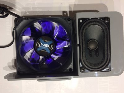
I did add a silent 80mm fan for the PCI extension area, mounted it to the original frame, set up as case fan to the mother board socket, done.
The original little speaker is presently not connected, I am tempted to figure out a sound module to resemble the Mac boot up sound, but that may me a “next time gimmick” for a while.
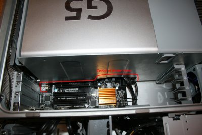
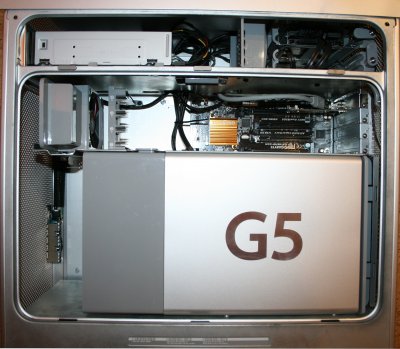
So finally my conversion is complete:
The nice processor cover snaps in place, air duct and fan holders back in place, hard disk frame in original position, DVD drive changed over to a SATA drive, also mounted in standard “Apple fashion”, all cables nicely stowed away, invisible for the very most part.
The system runs El Capitan alongside with W7 in dual boot with Clover EFI on a single SSD boot drive, a second 2.5 inch HD for data, very very silent, so I am very happy with the net result. Now I have to do a little search what type of stand alone graphics I may want to add, I want it to be SILENT, preferred without fan.
And side by side before and after:
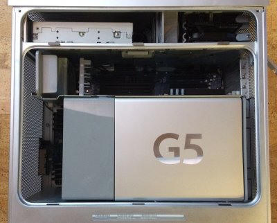


The whole work is very doable over a weekend, provided tools, some sheetmetal and parts available, the bigger thing though is to study other completed modifications ahead of time and take advantage of knowing the traps you may want to avoid BEFORE you spin up the Dremel tool.
P.S.:
A few hints and tricks which might be useful for other folks:
The main board (a Gigabyte H97) was already in service as Hackintosh system for a good year, in a decent, but not quite appropriate PC style case considering an almost all Apple household. So it was time to make it fit to an adequate case and here we go.
Here the core building blocks:
- Gigabyte H97M-D3H Motherboard
- Intel i5 3.3GHz Quad CoreProcessor
- integrated Intel HD Graphics 4600 == upgrade with additional Graphic Card in planning
- beQuiet cooling tower with 120mm low noise fan
- Kingston 2* 4 GB DDR3 RAM
- Kingston 240GB SSD
- Toshiba 1GB 2.5 inch HDD
- LG GH24N DVD burner
- no name 430W PSU
- Exsys EX 16450 firewire PCIe card (works OOB with El Capitan!)
- 2 NoiseBlocker XR1 60mm fans for the PSU
- 1 NoiseBlocker X1 80mm fan for the PCIe extension slot area
- Dual boot El Capitan/Win7 with Clover in EFI mode on single SSD


But first things first:
Converting the PSU was pretty much straight forward. Taking out the original power supply PCB, placing an ATX PCB on 4 short M3 standoffs, fixing the compensation inductor to the base, extending the power inlet wiring, a little shrink tubing, keeping the Apple noise filter in place and opening just a little space in the isolation rubber profile to feed out the ATX harness out of the case pointing straight up to where the ATX board has the connector. The 2005 model has solid copper bars feeding sideways to the motherboard, so that was kind of cool to use as a opening for the harness, no major metal work to be done. I replaced the original fans with NoiseBlocker 60 mm devices, which are providing enough airflow through the PSU case without nerve wrecking sound. The ATX supply was a no name 430W model with 120mm top blowing fan I had sitting on the shelve. This supply came with a whole bunch of cables for multiple disk drives, floppy drive, both SATA and IDE type of connectors but no cable management, so I was tempted to cut off all surplus wiring, by the end I did NOT and tugged them away in a corner of the pretty large Apple PSU box, just in case in need some for later.
One of the 12V/5V drive cables I cut down and left just ONE Molex socket to be available. The drive supply cable of the Mac (for hard disk and DVD drive) happened to be long enough to be rerouted to half way under the mother board, so adding a mating Molex pin header, voila, there is power in the drive compartment completely invisible.


Step two, preparing the motherboard mount.
As stated before I did want to keep as much of the “infrastructure” to keep the looks. Fortunately a mATX board fits very nicely when lining up with the extension slots and the front part of the original processor / fan holding structure can stay in position. In this 2005 model the processor mount structure is DETACHABLE from the body, in a matter of minutes you can take out the little metal frame, cut off the “backwards facing” part (see picture). After removal of some 3 or 4 standoffs, which don´t fit the ATX locations anyway you have a roughly 280 by 190 mm flat open space. While I had been grinding them away with a Dremel last time I tried a different method this time: Take a robust tube, which fits tightly over the studs and break them off the plate with some gentle wiggling, the studs come off very easily!
By virtue of the the very low mounting studs, which had been holding the detachable processor support plate you have now “built in” mounting positions for your ATX motherboard tray. So a piece of 1mm sheetmetal of 280 by 190 mm essentially needed holes for ATX standoffs and some holes for the “original processor support plate” pattern, and here we go, a mATX board is in position, detachable, no Epoxy glue or alike.


Step three, the rear panel.
My original intent was to also keep the rear in original shape, I had seen some modifications, where folks have come up with patch wiring and have put sockets in the original locations for USB, Ethernet, Audio and so forth. I tried hard, but by the end I gave up: The clearance between the ATX connectors and the physical metal of the Mac case is about 15 mm or even less, so any type of patch wiring will stick out of the connector panel by some amount, while a socket mounted to the Apple back panel extends some good amount to the inside, so you have to be in a very lucky position, that the connectors and the sockets don´t collide in the little clearance you have available. I failed, because the Ethernet socket of my mother board, which I did not want to loose collided with BOTH available RJ 45 openings in the original rear panel of the Mac. So bad luck and I instead made minimalistic rectangular cut out of the back, put some aluminum framing around the gap and reach directly at the ATX board.
I left the orginal fan grill structure in it´s position to be able reuse all the inner air guide structure and fan mounts! The trade off is minimal, I am losing two audio sockets, one USB and the VGA output, which I can easily live with.

Step four, the front panel.
This model came with a front panel, which holds a little PCB extension, which is directly attached to the logic board, not the classic cable harness version. The general recommendation I found in the forum was: Buy the cable version, sell off the PCB version, position and mount is compatible, cable version is passive, wiring harness for ATX conversion is well documented. Checking ebay for offers was a bit disappointing, cause the “cable version”, mostly even WITHOUT the pigtail runs at a premium price these day, so I felt like: “May I need to take a closer look at what I have”. Making the long story short the PCB contains a firewire transceiver and a number of other active components, which would interfere with a passive patch wiring to the connector pads. So I decided to take my little Dremel tool and simply cut off the part of the PCB, which held the active components. Then I also cut through the very fine traces leading away from the solder joints of the connectors at the firewire socket, at the USB socket. With a multimeter I validated that none of the relevant pads had remaining contact to any of the surroundings. Blocking caps or tantal´s hooked up to the 5V USB supply line or the respective firewire power don´t hurt and can stay. In the same course of action I found three adjacent pads on the backside, which lead to the tiny power switch power LED three pin connector. Next step was to find a set of cables with appropriate motherboard ATX pin headers. A decommissioned PC USB, audio... front panel was a decent donor, so I soldered my harness directly to the front panel backside solder pads of the connectors: Audio, USB, Firewire plus 3 single wires for power, common and LED. A tie wrap by the end keeps the harness in place without stress to the delicate solder points of the wire tips. So far I have tested USB, Audio and the power button / power LED, all working out of the boot, except that I could not get the power LED to work properly with my H97M ATX board. (it worked fine with an old generation P4 ATX board, which I had used for the mechanical prep work!) I figured out that the trouble maker is the fact, that the Apple circuitry uses a common lead for the switch and the LED return. The H97M ATX board (and likely similar with other brands and models!) wants the switch going from ground to the input terminal while the power LED want the LED connected to the positive rail and the output of the motherboard is an “open collector” pulling to ground. So ideally a 4 wire connection would be best, well not an option here. I fixed this conflict with a “one PNP transistor /2 resistor “ inverter circuit in the LED path, so that a common ground return for both power switch and power LED works again. The little circuit is shrink wrapped to the post type header. See some illustrations below. Remaining test will be to try the firewire front connector.


Finishing touches:
The divider frame of the original Mac is obviously designed around the original motherboard, with the mATX board in place the memory slots and some other components do collide a bit. Also the mounting point close to the PCI/PCIe slot ports at the rear panel no longer lines up. So I had to trim the divider frame at the motherboard side to provide enough clearance and I added a little sheetmetal bracket at the far end to line up with new ATX mount point. By adding a few washers to simulate the thickness of the motherboard the divider frame now sits exactly where it was in the first first place. The rear fan plastic frame collides with the the “connector towers” (USB, VGA, Audio and Network), but a healthy cut out of the bottom of the frame helps it. The frame snaps back in place being held by 3 out of 4 legs and on the inside there is even enough clearance to mount fans.
I decided to leave additional fans as option for the future, I also left this intake side without any fans for now. Instead I am using a giant beQuiet cooling tower with a single 120 mm fan and expect it will give me enough flow through the tunnel, considering both ports being completely open. I´ll do some temp testing later.
I also removed the two fans in the optical drive/hard disk bay. One of the fans is a radial blower geared at the G5 heat pipe on the bottom side of the motherboard, that is simply obsolete, cause there is no active circuitry on the backside of an ATX board. This opens the opportunity to feed the power supply harness for the drive under the motherboard through an existing hole of the drive bay compartment, no metal work required! The second fan creates some flow across the drives, frankly I am using an SSD as boot drive which does not run as hot as a 2005 hard disk, so I can get away without any fan in the top level compartment. Yet I have put the empty frame back in place to keep the outer appearance. What the radial blower removal also gives you is a very straight forward routing path for the SATA cables to the mother board, otherwise it would be real tight I the upper compartment!
I did add a silent 80mm fan for the PCI extension area, mounted it to the original frame, set up as case fan to the mother board socket, done.
The original little speaker is presently not connected, I am tempted to figure out a sound module to resemble the Mac boot up sound, but that may me a “next time gimmick” for a while.


So finally my conversion is complete:
The nice processor cover snaps in place, air duct and fan holders back in place, hard disk frame in original position, DVD drive changed over to a SATA drive, also mounted in standard “Apple fashion”, all cables nicely stowed away, invisible for the very most part.
The system runs El Capitan alongside with W7 in dual boot with Clover EFI on a single SSD boot drive, a second 2.5 inch HD for data, very very silent, so I am very happy with the net result. Now I have to do a little search what type of stand alone graphics I may want to add, I want it to be SILENT, preferred without fan.
And side by side before and after:


The whole work is very doable over a weekend, provided tools, some sheetmetal and parts available, the bigger thing though is to study other completed modifications ahead of time and take advantage of knowing the traps you may want to avoid BEFORE you spin up the Dremel tool.
P.S.:
A few hints and tricks which might be useful for other folks:
- OSX has the “built in” eject button in the info bar and the special key on the keyboard, Windows usually relies on the physical button of the optical drive. Yet the nice drive door mechanism of the Mac case does not give you access to the physical button! I found several free utilities for Win to help this, personally I have installed HiCDEJECT, which simply adds a little icon in the info tray of Win, touch it and the tray opens and closes
- Dual boot messes with time zones! Mac OS works with UTC, Windows uses GMT, both poke around with the BIOS clock, the net is confusion. Go fix this by having Windows also reference to UTC, it merely is a minor change in the registry. (help available in the forum)
- Getting the radial blower out of the drive bay compartment seemed to be very difficult in the first place, cause the space is very very tight. By the end I figured out, that the little blower is only snapped in place on 2 studs, so gently pull it up and THEN take the bottom mounting screws out of the chassis, the separated pieces can be taken out just easily.
- The 2005 G5 front panel is also snapped in place rather than held down with a couple of screws. Took me a while to get it off: Take a little metal tube with a 4mm diameter, push it gently over the ends of the clamping studs to release the front panel, it comes off in seconds! Saw service instruction videos grabbing the ends with pair of pliers, did not work for me, cause you really need the grab the four prongs of the clamp studs in one go all around.
- Taking out the original processor module from the motherboard was another little tricky part: You need some really really long Allen drivers to reach through the big and high cooling tower to the bottom 2 center bolts, my local hardware store did not have those extra long thingies on stock. Standard bit holder type of tools however are to big to enter the hole in the cooling tower. Well, I helped myself by simply taking a stand alone Allen bit, grinded a slot into the back of the bit. Now I was able to dump the bit into the hole in the cooling tower and take a regular long screwdriver as an “extension” reaching to the slot in the back of the bit, the processor was off the motherboard in a minute.
Last edited:
