Contribute
Register

BoomR's twist on the G5 Front Panel Quick Guide

Status
Not open for further replies.
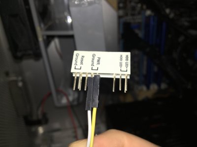
Hey BoomR, thanks a lot for posting this. It has been really helpful. My G5 mod is in progress and I hope to post it as soon as I finish. I'm confused about some of the wiring for the front panel and don't want to short the motherboard. Looking at your color-coded diagram, it looks like only 5 jumpers are needed for USB, 9 for FW, and 4 for audio. Is this correct?

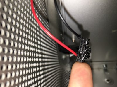
Also, for the FW header, theres two number 2s and 1s. Do I attach two jumpers to the number 2 wire of the G5 connector when I solder for these? (1 cable coming from G5 to 2 cables going out?)

And.. regarding the jumpers that 'ground' the headers (such as USB GND, USB Shield Ground, FW GND, etc), is it fine to use regular jumpers for these or is there something specific I need to use to shield them?
 
This is a very helpful guide, thank you, I am not planning on using the Firewire or audio so is there anything I should do differently? I have currently just got the USB wired up and plugged into another computer for testing and when I plug a hard drive into it I get the power LED lighting up on the drive but no recognition of the drive on my computer :( any ideas?
 
Sorry for bringing up this old thread, but I reckon there might still be people working on this as it's still a beautiful classic case.

All works like the TS mentioned, only I had to switch a few wires for my Z68X-UD3H-B3 to make the USB working. On the USB header, I swapped 2-8 for 1-7, so 2=1, 4=3, etc. I left 10 in place, although I doubt it's needed:

g5-front-panel-diagram-annotated-jpg.42439


Hope this helps others as well :)
 
Hi, you're right. There are still people modding the G5 ;)

I could use some help with the wiring. The whole "which way to look at it" totally confused me. Currently, only my power button is working. The thing is, I wired it with the wrong point of view in my mind: I understood the G5 Front Panel Connectors' Wiring Diagram (the one with the 18 numbers we've all seen a lot) as if I held the black plastic connector in my hands and looked at its' "bottom" (which I shouldn't according to "BoomR")

But this HAS to be the right perspective, because it WORKS! When I connect it as advised ("as if the black connector was attached to the motherboard and you look at it from the top", I get NO connection. Check out the pictures below. I named them, so you understand what I'm talking about.

If someone can help understand the wiring and finally get the PLED to work, I'd be so happy ;).

edit: Seems like the forum won't display the images' names. So, in the upload order, their names are:
1. Breadboard for Extension from Front Panel to Mainboard (just because the wires are too short)
2. Connector to Motherboard
3. SupposedlyCorrect (as advised by BoomR)
4. SupposedlyWrongButWorking
5. Overview_WORKING (but supposedly wrong)
 

Attachments

  • Breadboard for Extension from Front Panel to Mainboard.JPG
    Breadboard for Extension from Front Panel to Mainboard.JPG
    1.8 MB · Views: 352
  • Connection To Motherboard.jpg
    Connection To Motherboard.jpg
    1.9 MB · Views: 384
  • SupposedlyCorrect.JPG
    SupposedlyCorrect.JPG
    2.1 MB · Views: 395
  • SupposedlyWrongButWorking.JPG
    SupposedlyWrongButWorking.JPG
    1.8 MB · Views: 412
  • Overview_WORKING(SupposedlyWrong).JPG
    Overview_WORKING(SupposedlyWrong).JPG
    3.4 MB · Views: 366
Hi, you're right. There are still people modding the G5 ;)

I could use some help with the wiring. The whole "which way to look at it" totally confused me. Currently, only my power button is working. The thing is, I wired it with the wrong point of view in my mind: I understood the G5 Front Panel Connectors' Wiring Diagram (the one with the 18 numbers we've all seen a lot) as if I held the black plastic connector in my hands and looked at its' "bottom" (which I shouldn't according to "BoomR")

But this HAS to be the right perspective, because it WORKS! When I connect it as advised ("as if the black connector was attached to the motherboard and you look at it from the top", I get NO connection. Check out the pictures below. I named them, so you understand what I'm talking about.

If someone can help understand the wiring and finally get the PLED to work, I'd be so happy ;).

edit: Seems like the forum won't display the images' names. So, in the upload order, their names are:
1. Breadboard for Extension from Front Panel to Mainboard (just because the wires are too short)
2. Connector to Motherboard
3. SupposedlyCorrect (as advised by BoomR)
4. SupposedlyWrongButWorking
5. Overview_WORKING (but supposedly wrong)
Ok, to take your confusion away (I had it too), looking at BoomR's drawing:
- The G5 front panel connector is shown from the bottom, so the part of the connector that is directly attached to the little connectorboard is the closest in this view. Also keep in mind the nodge on the side.
- The USB, Firewire and Audio headers are shown from the top, so actually you are looking at the connections on the motherboard.

I have tried to rewire it too, that resulted in a computer dat goes on straight or doesn't boot, so that's definitely wrong ;) Also, the power button/LED is fed by the USB GND, so make sure to attach that as well.

I tried to make this a simple thing in this thread, see post 29: https://www.tonymacx86.com/threads/neilharts-completed-case-mods.87399/page-3

In the case of the HD Audio we are mashing old tech with current tech found on today's motherboards. The G5 front panel audio jack receptacle just does not have the appropriate contacts to support auto sense. For the hard core modder, you can actually remove the old jack and epoxy in a current tech audio jack receptacle.

Good modding,
neil
Great work! Ik actually never use the headphone jack, so I actually don't bother ;)
 
Finally got it working! My main fault was that the many wires on the breadboard weren't wired correctly. I bought some extra jumper wires and connected everything directly without the breadboard. Voilá!
Let's see if I can get USB and Audio working soon when I have some time.

In order to finally put away with the "perspective confusion" I prepared this picture:
 

Attachments

  • Explanation.jpg
    Explanation.jpg
    1.8 MB · Views: 527
You put that on ground for example FW GND (PIN2). I did not try it but probably the PIN10 USB GND works too.

Please correct me if I am wrong here.

Thanks
 
Status
Not open for further replies.
Back
Top