Contribute
Register

BoomR's twist on the G5 Front Panel Quick Guide

Status
Not open for further replies.
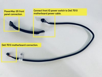
Hi BoomR, thanks for your helpful front panel guide. This will be my next project for my BlueG5 build. But I'm not electrically minded and things can easily go wrong. So answers will have to be in layman's terms. My question is using the wiring diagrams included here for the front G5 panel. And trs96 helpful motherboard power switch connection pinout guide for the Dell 7010. Can I connect these two cables?.

IMG_0980.jpg


07010PowerSwitchPinOut.jpg.5e1fd0b37e6dcf084926e4762262e881.jpg
 

Attachments

  • IMG_0980.jpg
    IMG_0980.jpg
    238.4 KB · Views: 1,312
  • 07010PowerSwitchPinOut.jpg.5e1fd0b37e6dcf084926e4762262e881.jpg
    07010PowerSwitchPinOut.jpg.5e1fd0b37e6dcf084926e4762262e881.jpg
    44.7 KB · Views: 189
Finally got it working! My main fault was that the many wires on the breadboard weren't wired correctly. I bought some extra jumper wires and connected everything directly without the breadboard. Voilá!
Let's see if I can get USB and Audio working soon when I have some time.

In order to finally put away with the "perspective confusion" I prepared this picture:

Excuse me, but this kept puzzling me for a long time. Either this is true or Eelhead's description is ("View shown here is 'top down' of multi-pin connector while connected to the motherboard. (not 'bottom up' after disconnecting from the motherboard)").

IMHO, what @tulpixo's picture is showing, is the 'bottom up' connector after disconnecting from the motherboard.

Basically,
@tulpixo says: the diagram = looking into the 'female', open side of the cable of the connector plug.
@eelhead says: the diagram = looking from the with-wire-filled side of the cable connector.

It took me quite a while to figure out that: Assuming all 'digital data' wires (FW TPA-, FW TPA+, FW TPB-, FW TPB+, USB + and USB -) have the same thickness / are thinner than the ground, power and analog wires and looking at the original connector-cable, the only logical conclusion can be that the diagram represents the open side of the wire.
 
Status
Not open for further replies.
Back
Top