Contribute
Register

Bluetooth A1114 Voltage Regulator Build

Status
Not open for further replies.
I did see that thread but couldn't figure out exactly how to do that and where the 3.3v was exactly so the solution I chose was the easiest for me (and cheaper actually.. I only used compenents I owned ;) )


bye! :p
 
actually I found the pinout on the second page! (I did stop reading at the first last time.. no time.. :p )

next time I open the PC I check if I can confirm the 3.3v is where they say and in that case I can maybe use that rather than the component fix thanks ;)

byeeee
 
moly82 said:
actually I found the pinout on the second page! (I did stop reading at the first last time.. no time.. :p )

next time I open the PC I check if I can confirm the 3.3v is where they say and in that case I can maybe use that rather than the component fix thanks ;)

byeeee

Ya I have mine running of the PCI-e card and its nice and clean looking. That's the only reason a even mentioned it. Also you might have to scratch off some of the green PCB board paint to see the gold circle contact. (At least I had too)
 
i bought 2010 imac bluetooth module bacause a1114 module not supported windows 7 64bit edition. but its' pin out was different from a1114 BT board.
a1114 BT cable is 4 lines(power, +data, _data, ground)
2010 imac BT cable is 5 lines(?,?,?,?,?)

anybody knows the pin out?
 

Attachments

  • bluetoothboard.png
    bluetoothboard.png
    294.5 KB · Views: 936
Check HERE at post #18. It looks like the same board with yours but his connector has 4 cables. Compare them to find out which pins to use. At next post there is the pinout.
 
moly82 said:
here is my final project at last :)

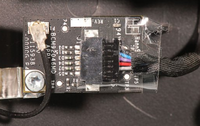
thanks to the help of the R&D department personnel in the company where I work I made this 5v to 3.3v regulator.. now I have always a perfectly stable 3.3V to the BT :) no more 4.1V to it when the PC is turned OFF so I am peaceful now :p
I used a component plus a couple of capacitors and connected everything to the USB header on the motherboard.. the BT components are fixed to the wi-fi adapter with pretty strong doublesided tape.. the third unused antenna that came with the wi-fi adapter is now connected to the BT board

I am attaching pictures of the regulator mod and the final assembly.. thanks to all for your info and help keep sharing! :)


Uploaded with ImageShack.us
Moly please can you tell me what parts you used to make the regulator. I don't want to purchase a regulator. Want to make my own like you. Thanks in advanced.
 
Gus said:
Moly please can you tell me what parts you used to make the regulator. I don't want to purchase a regulator. Want to make my own like you. Thanks in advanced.


the component is called LT1528, and a couple of capacitors.

see the pic for the pinout, I hope it is readable.
all the rights to the R&D department people where I work, I have just put all togheter and make the solderings.. :)

bye!


Uploaded with ImageShack.us
 
Thanks are those 10 PICO Farad capacitors? And just tie them to both the input and output lines to ground?

Thanks a bunch
 
Gus said:
Thanks are those 10 PICO Farad capacitors? And just tie them to both the input and output lines to ground?

Thanks a bunch

yes but it is not so important to have the 10 pF.. for example I put 33pF on one side and 47pF on the other side instead of 10pF in both and everything works fine ;)

I did sold the + end to the component pins (1 and 5), and the - end to the GND on the left of the component (where is written tab is ground ;) )

bye!
 
Are you sure that these capacitors are 10pf (picofarad) and not 10uf (?f microfarad)??
 
Status
Not open for further replies.
Back
Top