Contribute
Register

Kiwi's Next Project - iMac G5

Status
Not open for further replies.
Part 20 - Temp Inputs

My original design called for two TMP36 temperature sensors, to monitor and control fan speeds. I Tested this over the last few days, and basically couldn't get it to work, temperatures were all over the place.

The solution was to replace the sensors with DS18b20 sensors, the major difference between these two sensors is that instead of an analog voltage output, the DS18b20 has a one wire serial bus. Physically both sensors look identical, like small three pin (Vcc, Gnd, Signal) transistors.

Thus the change to my SMC board was simple, just route the Signal pins of the three pin header sockets to a single digital pin (and include 4k7 pull-up resistor), rather than two analog pins, and finally change the software.

So now have fan control based on temperature differential between sensor mounted at the bottom of the case near an air inlet, and top mounted sensor near intake of the main exhaust fan. Temps register about a 6 degree differential when system is idle.

NOTE: This change was made in a REV 1.3 to the board design which can be found in the Bill of Materials here
https://github.com/kiwisincebirth/iMacG5

Startup Chime

My original design was to use the ISD 1820 voice recorder module to provide a startup chime, I based this on other reports (on this forum) of its use.

The module is not fit for my purpose, the quality of the recording is very poor and the internal amplifier provides very little volume. My bad for not testing it upfront. I have dropped it from my build, it was a nice to have anyway. . .*

Kiwi
 
Can we get the Fans PWM signals from UNC mainboard conversion the voltage to MAC G5 FANS?
 
didnt read the whole thread sorry.

But I would like to do a nuc in the future in my donated g5.. it seems to be working but I need to reset the thing which is becoming a pain without the original disk. anyone know where to get a powerpc copy of leopard?

also was thinking about using the imac as external display .. did you find anything about hooking into the display wiith dvi or vga?
 
Can we get the Fans PWM signals from UNC mainboard conversion the voltage to MAC G5 FANS?
I am sure its possible, but not needed for my build. I think NUC fans run at 5V, so you would need a power transistor to switch a 12v source from the PWM signal on the nuc. The big difference with G5 fans is the PWM input carries the main power input. See this post for everything I know.

http://www.tonymacx86.com/imac-mods/107859-kiwis-next-project-imac-g5-4.html#post681755
 
didnt read the whole thread sorry.

But I would like to do a nuc in the future in my donated g5.. it seems to be working but I need to reset the thing which is becoming a pain without the original disk. anyone know where to get a powerpc copy of leopard?

also was thinking about using the imac as external display .. did you find anything about hooking into the display wiith dvi or vga?
I would try eBay for copies of Leopard.

Yes it would be possible, you need to read through the entire thread, here are a couple of the main ones to read. Note: To make it work, you need a PSU capable of 3.3v 12v and 24v to power the LCD and inverter, and also a brightness controller.

http://www.tonymacx86.com/imac-mods/107859-kiwis-next-project-imac-g5-3.html#post661004
http://www.tonymacx86.com/imac-mods/107859-kiwis-next-project-imac-g5-7.html#post763190
 
thx kiwi! You are a true inspiration. I found time to chug through this beast of a thread... and ur work is stunning. smc ... im speechless bro. id say you embody what it means to hackINTOSH. keep it up!
 
PART 21 - Capacitive input

Here are the details of my capacitive input sensors
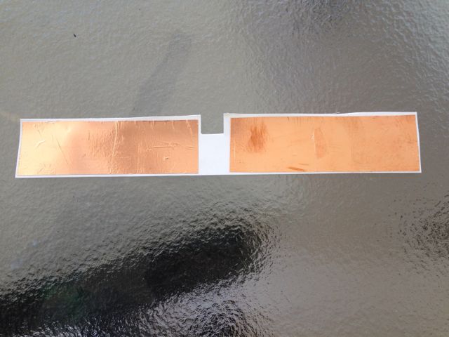
I used copper tape stuck to create the two sensor, these were stuck to a sheet of plastic.
IMG_2996.jpg


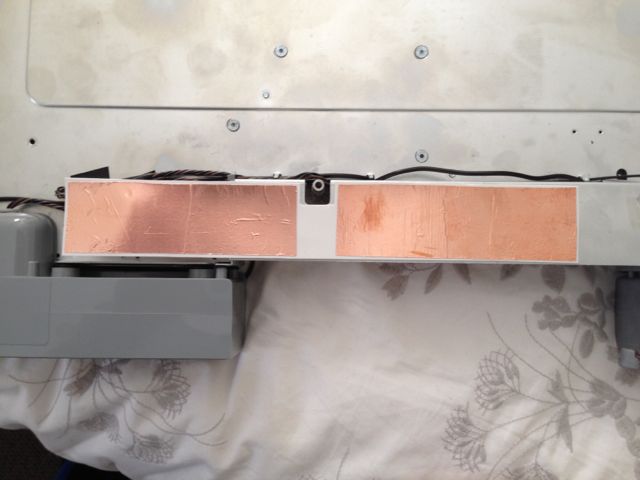
The sensors were placed underneath the main PSU, the photo (below) is viewed from the font of the computer, where the sensors are to the left and right of the main apple logo. Note for Context, you can see the back of the four mounting bolts for the SMC, above the sensors
IMG_2998.jpg


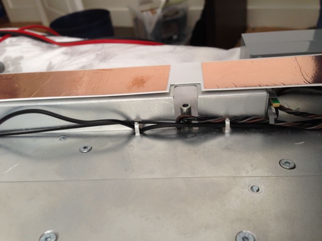
Shown from another angle, looking from the top of the computer.
IMG_2999.jpg


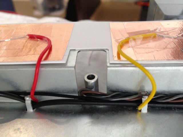
I connected bare wires to the copper tape using sticky tape. The bare wires extend for most of the length of the copper tape.
IMG_3003.jpg


Tested and for the most part work, although I do have issues with the reading from one of the sensors, getting higher and higher (with each reading). It requires a constant re-calibration (zero reset). I haven’t investigated this issue further, so for the moment have disabled the sensors.

Kiwi

thx kiwi! You are a true inspiration. I found time to chug through this beast of a thread... and ur work is stunning. smc ... im speechless bro. id say you embody what it means to hackINTOSH. keep it up!

Glad you enjoyed the read.
 
Expect updates!

Part 22 - Breathing LED

There has been some work done on describing the breathing led on this forum, so thought would document my implementation. From what I have read there is a 5 second cycle, where the first 1.5 seconds is the fade up, and then 3.5 seconds fade down to zero. From my observations there is also a gap at the end of the fade down, and the start of the next fade up.

Here is the final result

[video=youtube;Lc9jbCLcccQ]https://www.youtube.com/watch?v=Lc9jbCLcccQ[/video]

I based my fades based on simple sin/cosine function to achieve a more organic feel, in the first 1.5 seconds a simple son/cos function is used to ramp up from minimum to maximum. Then the same sin/cos function at the end in the fade down.

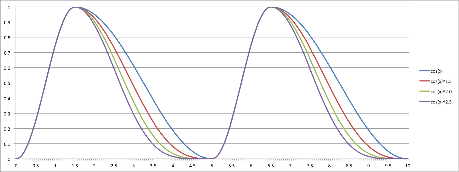
To achieve a gap at the end of the fade down, I raised the result of the sin/cos (value from 0 to 1) to a power of a constant. The higher the constant the quicker the tail off and the longer pause before the next ramp up occurs.

The image below shows the effect of altering the power the function is raised to

Breething LED.png


I chose a power of 1.8, for my final implementation.

Below is the striped down code that shows how it works. The important part is the computeBreath() function which converts a time input to an output between 0 to 1, representing the intensity of the LED. The code uses SimpleTimer to schedule (as a background thread) the change the LED every 5 milliseconds

Code:
#include <SimpleTimer.h>

// PIN TO USE
const byte SLEEP_LED_POUT = 3;

// A general purpose timer
SimpleTimer timer = SimpleTimer();

// 
// ========================================
// MAIN ARDUINO SETUP (1x during startup)
// ========================================
//

void setup () {
  
  // LED setup
  digitalWrite(SLEEP_LED_POUT,LOW);
  pinMode(SLEEP_LED_POUT,OUTPUT);

  // A timer is created to animate the LED  
  timer.setInterval(5,ledBrightnessCallback);
  
  // enable the effect
  activateFrontPanelLEDBreath();
}

void loop () {
  // Let the simple timer run any backgound tasks
  timer.run();
}

//
// ----------------------------------
// Front Panel LED Control - OUTPUT
// ----------------------------------
//

const byte LEDMODE_NORMAL = 0;
const byte LEDMODE_BREATH = 10;

byte ledBrightnessMode = LEDMODE_NORMAL; // are we using any special features
unsigned long ledEffectStartTime = 0; // when did the effect start
unsigned long ledEffectDuration = 0; // is there a duration of the effect (fade)

byte targetLEDBright = 0; // what the brightness should be, smoothing

void activateFrontPanelLEDBreath() {
  ledBrightnessMode = LEDMODE_BREATH;
  ledEffectStartTime = millis();
  ledEffectDuration = 0;
}

// -------------

// Callback function actiually sets LED brightness Called every 5 msec
void ledBrightnessCallback() {
  
    if (ledBrightnessMode == LEDMODE_BREATH ) {
      targetLEDBright = floatToPWMWithOffset( computeBreath( millis()-ledEffectStartTime ) );
    }
    
    // actual write of the PWM Value
    analogWrite(SLEEP_LED_POUT, targetLEDBright );
}

/**
 * Breathing LED effect brightness compute brightness
 */
float computeBreath(unsigned long timeInCycle) {
  
  // how much time has elapsed in the 6 second breath cycle. 0 - 2
  long timeInBreathCycle = timeInCycle % 5000;
  
  if ( timeInBreathCycle <= 1500 ) {

    // simple cos roundng    
    return computeTrigFactor( (float)timeInBreathCycle/1500.0f );
  } else {
    
    // convert to a decreasing value from 1 to 0
    return pow( computeTrigFactor((float)(5000-timeInBreathCycle)/3500.0f), 1.8f );
  }
}

/**
 * Computes a Trig Function 
 * Input - Value between 0 and 1
 * Output - Value between 0 and 1, with cos smoothing
 */
float computeTrigFactor( float input ) {
  return cos(input * PI + PI) / 2.0f + 0.5f;
}

/**
 * Converts Float 0 to 1 to PWM value 0 to 255
 */
byte floatToPWMWithOffset( float value ) {
  if ( value <= 0.0f ) return 5;
  if ( value >= 1.0f ) return 255;
  return value * 250.0f + 5.0f;
}

EDIT: The full code can be downloaded from here - https://github.com/kiwisincebirth/iMacG5

Kiwi
 
Status
Not open for further replies.
Back
Top