- Joined
- Nov 25, 2010
- Messages
- 1,211
- Motherboard
- AsRock X570M Pro4
- CPU
- Ryzen 3700x
- Graphics
- RX 580
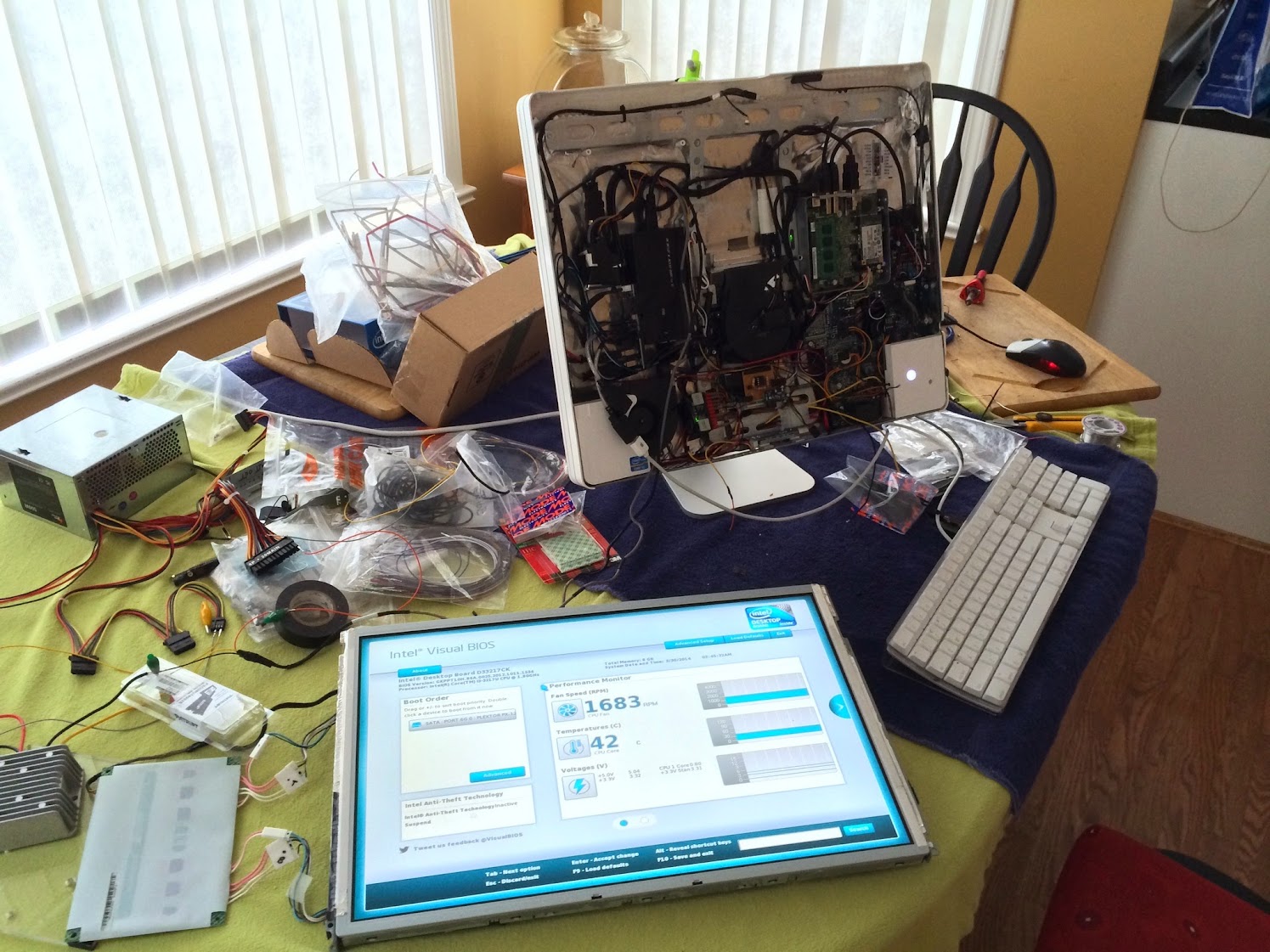
This is astounding work so far, can’t believe how quickly you move from one project to another. Looks like this machine was a big re-design from the one I am doing. Very different challenges.
Some feedback:
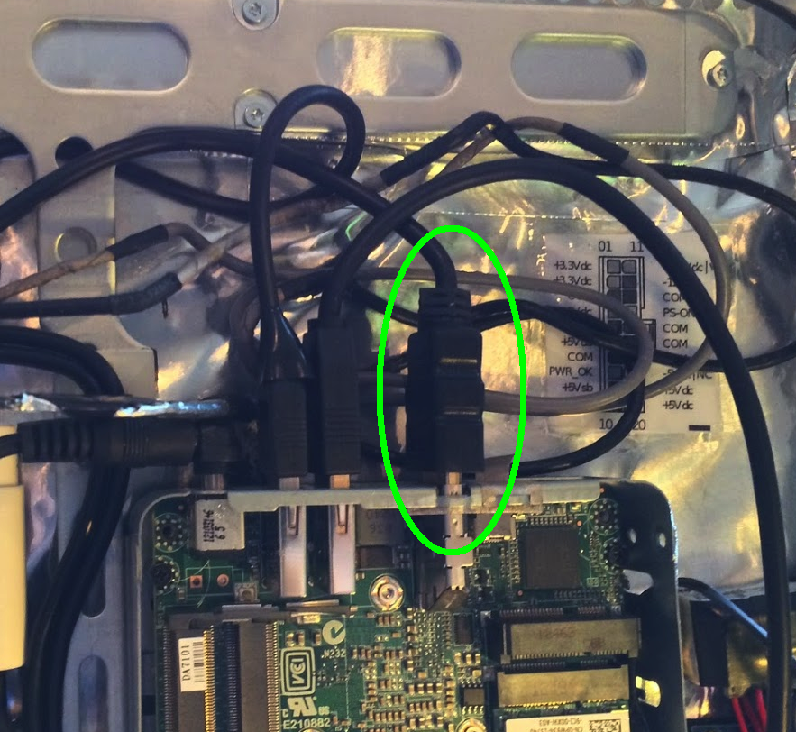
PSU / Inverter
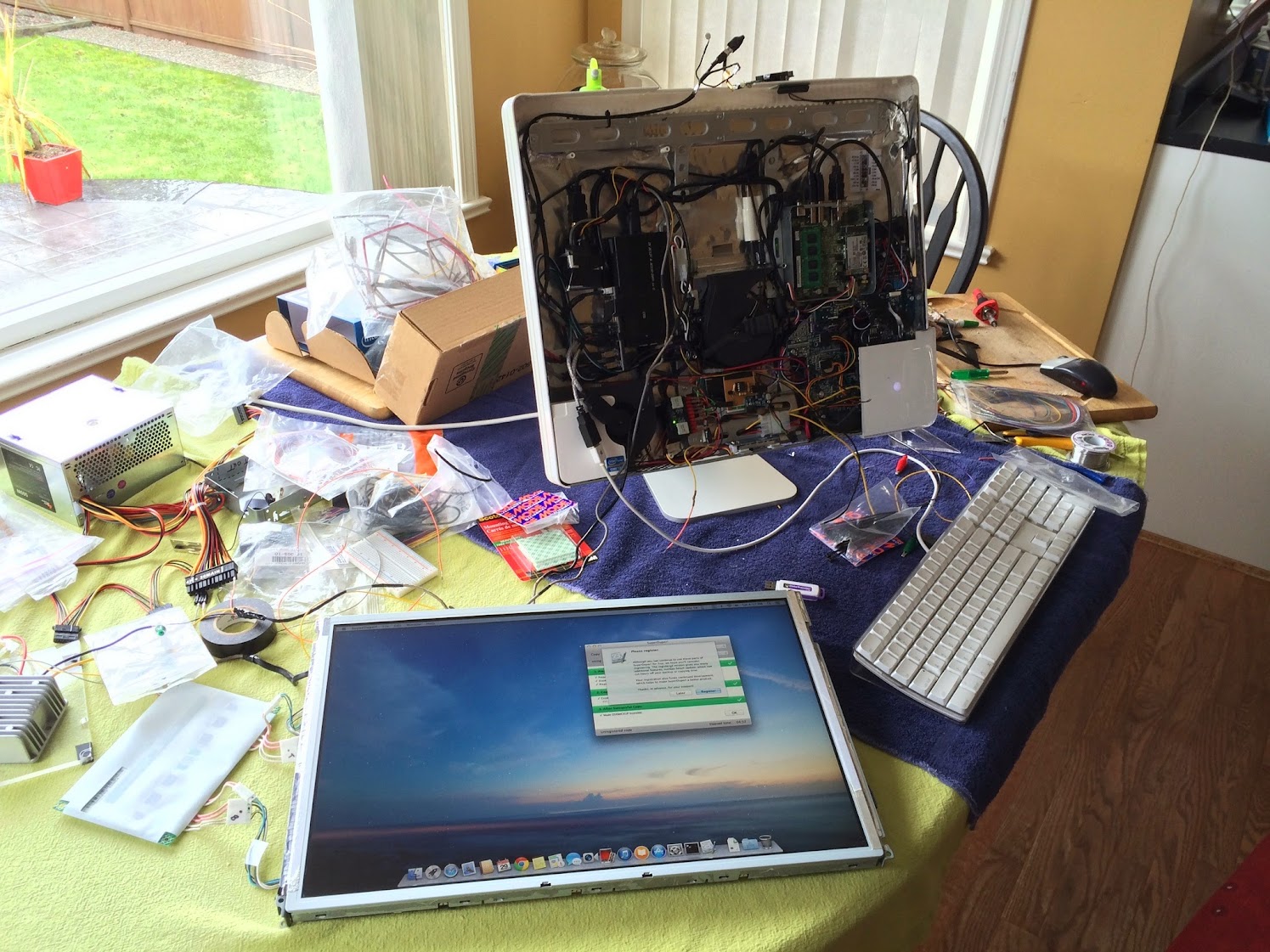
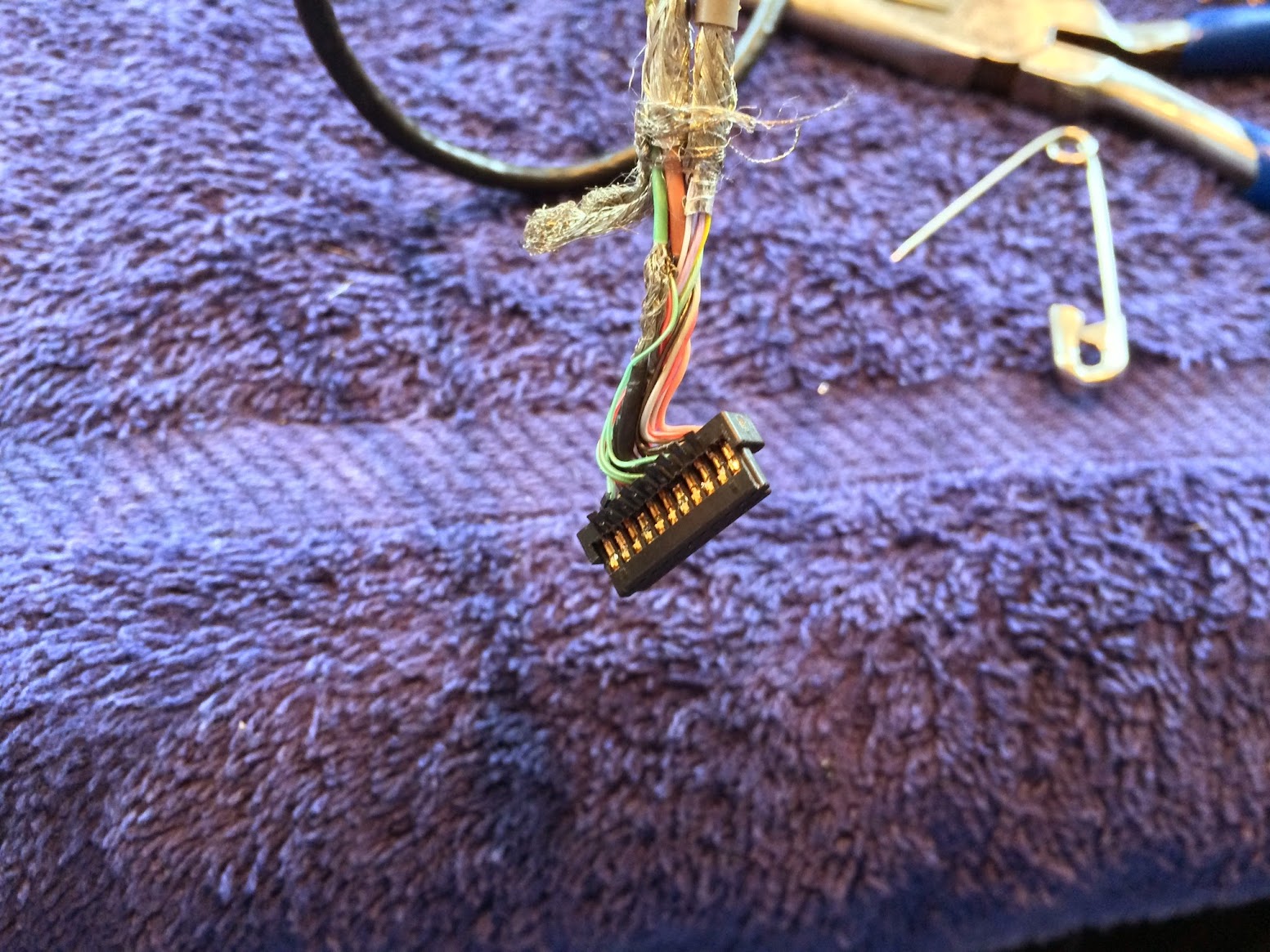
The combined inverter-DC power supply must have a way of being controller by software, looking at your picture of the board it looks like there are three cables, one of which (I assume) is connected to the main logic board. my guess would be that one of the pins in this cable provides the PWM signal from the logic board to the inverter.
To reuse the PSU, would need to just map out the PINS on the cable that links to the logic board, find the appropriate power and control signals.
As for re-using an old PSU, in my project I have measured the wattage on wall socket and at peak usage, is less than half the rated capacity of the PSU. While not nothing this will put less strain on PSU, and help prolong its life. Cant speak to issues
As for your solution, should work perfectly.
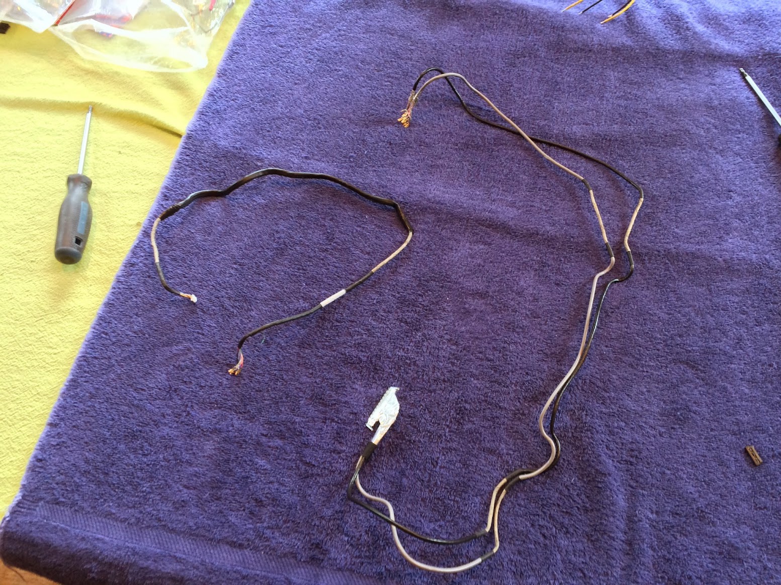
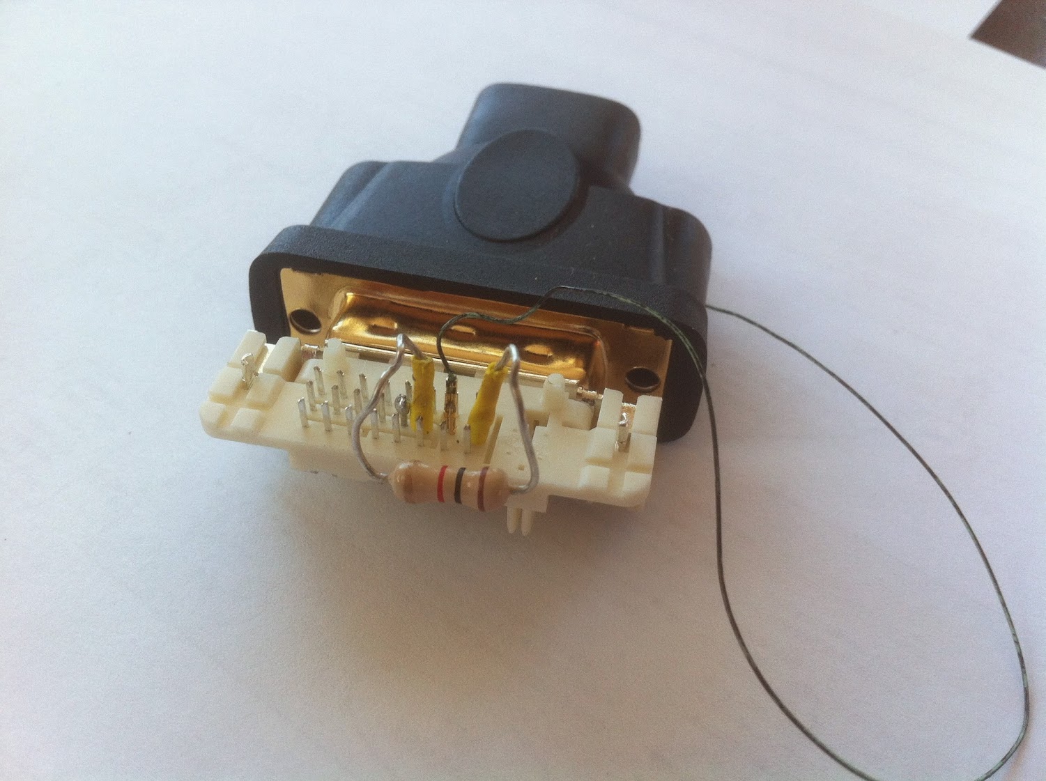
Front Panel LED
You note that the LED is very bright, I would consider putting a resistor of a higher value in series with the LED to limit the current, reduce the brightness, and extend the life of the LED.
Kiwi
Hello Kiwi, your points are very good. You're idea that one of the wires in the Logic Board connector carrying the PWM signal is probably right. The inverter has to be controlled somehow, this is probably it. I applaud your re-use of the original PSU, I'm assuming yours is in much better condition than this one was... it looked close to death.
I've already added a resistor to the line. Be careful with the iMac LED. Dont go any higher than a 3.3V supply with it. I was playing around with a 17" G5 junker here and toasted the LED with 3xAA size batteries (around 4.2V measured output). It flashed 3 times, dimmer each time and went dark. I didn't need it anyway, was just testing it out. Careful with yours...
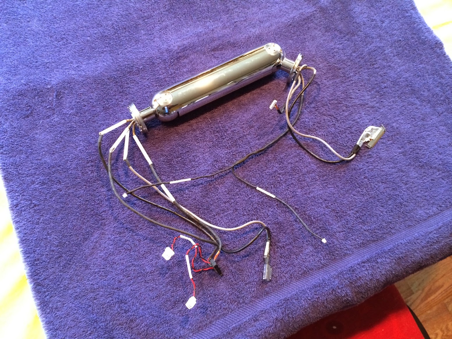
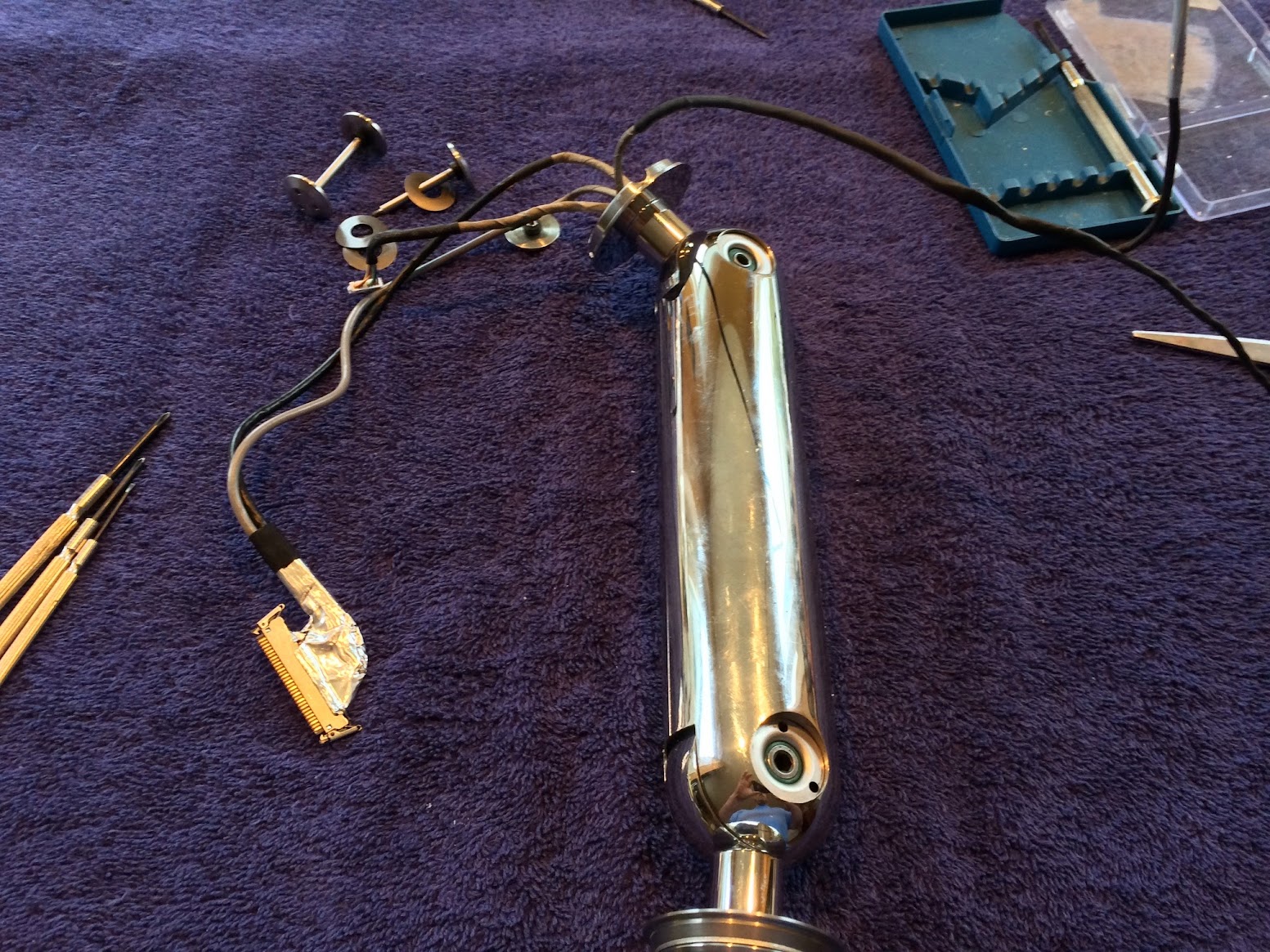
I hope you're right about my proposed solution actually working. Going to test it tomorrow. The 20" iMac neck arrived today.
Cheers!


")