Contribute
Register

Uncut G4 Cube Mod ( ongoing project)

Status
Not open for further replies.
Joined
Jan 28, 2012
Messages
166
Motherboard
Intel Nuc
CPU
Intel Core I3
Graphics
Intel HD 4000
Mac
  1. iMac
  2. MacBook Air
  3. Mac mini
Classic Mac
  1. 0
Mobile Phone
  1. iOS
Intro.

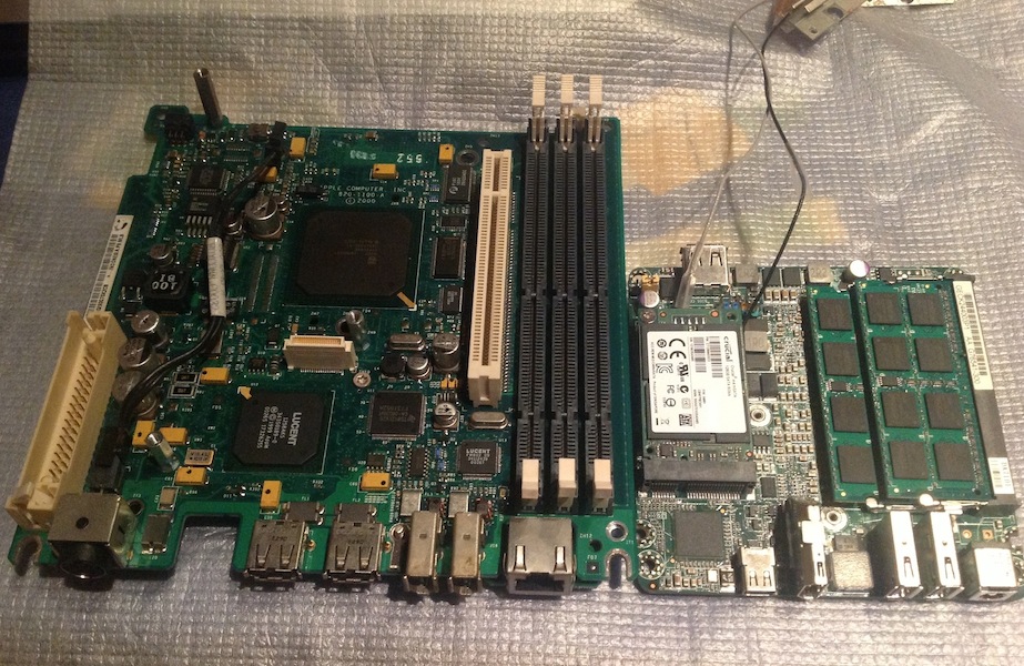
I own a stock G4 Cube and like many others wanted a modern Intel version .So years ago I bought a non-working Cube (core only) with the intention of fitting the internals of an Intel Mac mini.
The project was put on hold indefinitely for several reasons: lack of skills, time and the most important one: the Mac mini form factor changed making the project close to impossible for me.

I knew that it was time to restart the project when I read about the Intel NUC motherboard in http://www.dremeljunkie.com ( superb iMac g4 modding source of information).The NUC 4" x 4" form factor was ideal but would it be able to run MacOS X ? Of course!


Acknowledgements

Before going any further I would like to thank jberg44 ( the dremel junkie) , MacTester57 and all the Cube modders comunity for the inspiration.

Thanks to SynGatesFan200 and specially to faithie999 for their help with the the Mountain Lion install.

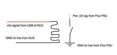
Thanks to minihack and rossi1959 for their help with the power switch.


Project 's goal

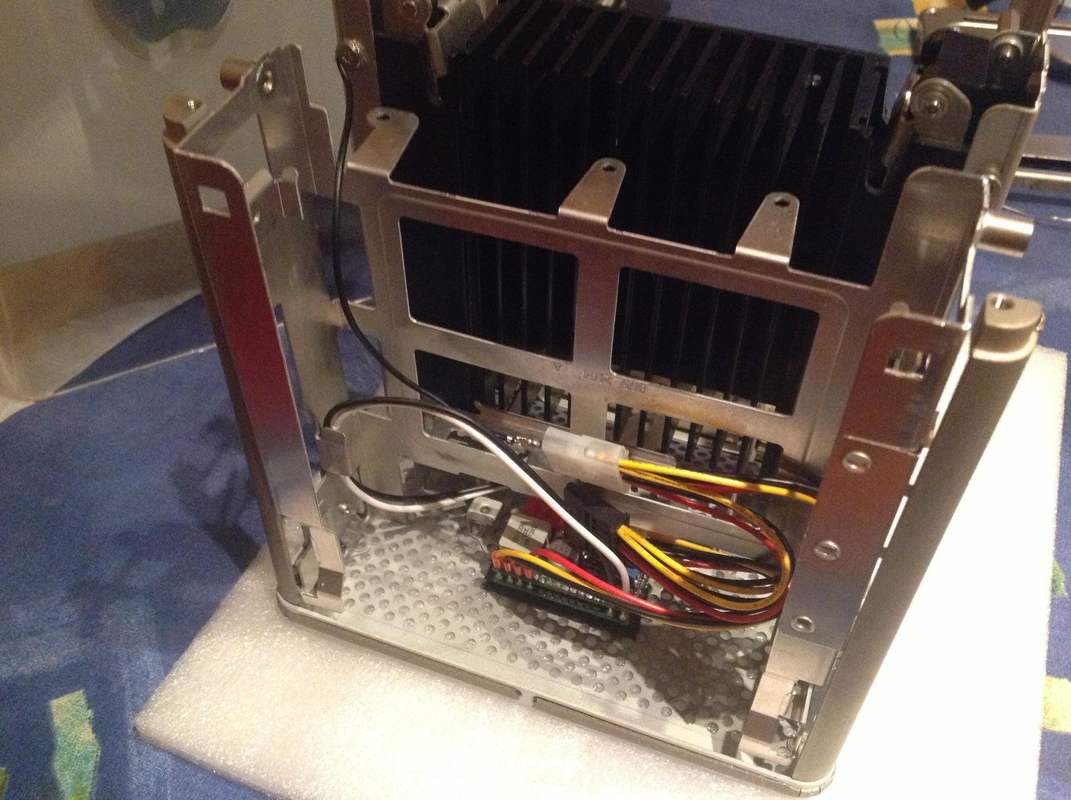
My goal is to modernize the G4 Cube without any major alteration. This means no heatsink removal and no I/O ports cutting.
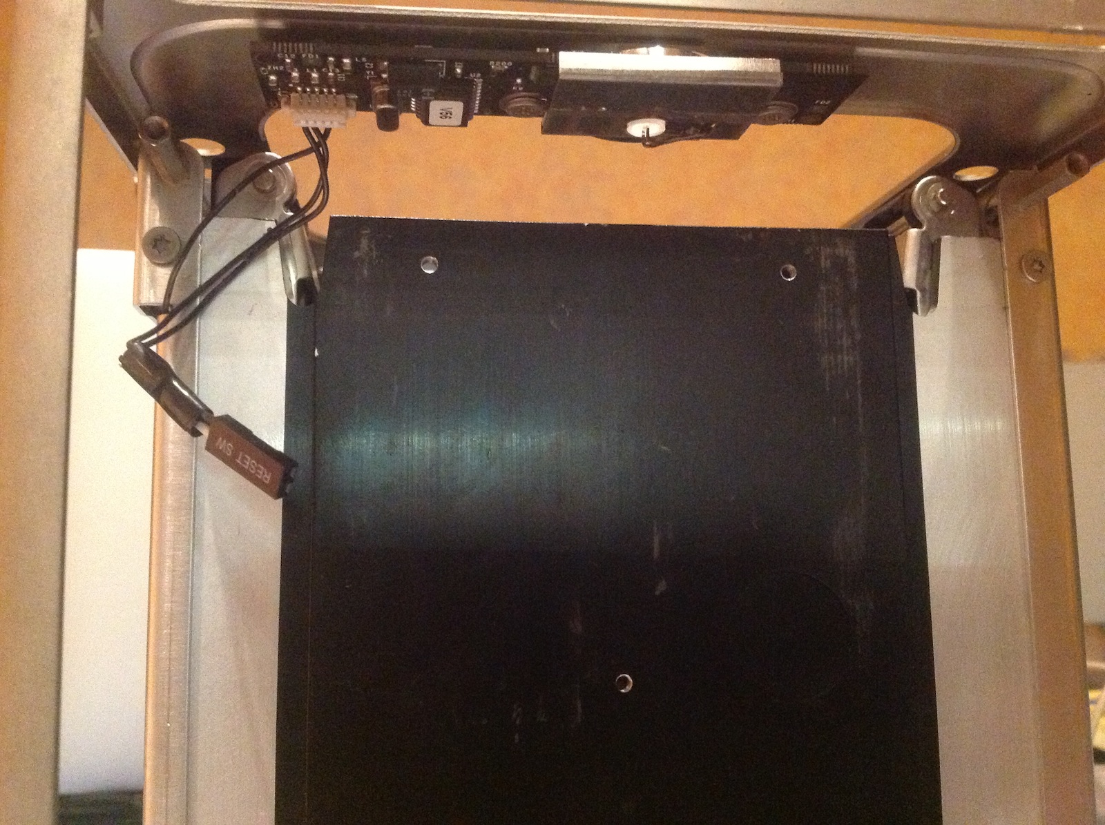
The Cube will keep its original features: fanless, sensitive power switch and the slot loading optical drive.


Hardware

- CPU Intel Core i3-3217U dual core with HD4000 Graphics
- Intel Next Unit of Computing Board D33217CK
- RAM Crucial 2x4GB
- mSATA SSD Crucial 128 GB
- MBP 922-7195 infrared board
- DELL DW1702 ATHEROS AR5B195 HALF-MINI WIRELESS N + BT BLUETOOTH COMBO MINI-CARD (BT doesn't work properly with Apple Devices)
- IOGEAR Bluetooth 4.0 USB Micro Adapter GBU521
- Original G4 Cube power switch
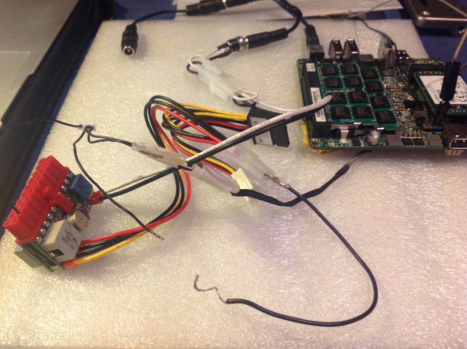
- PicoPSU-120-WI power supply 12-25V 120W
- Impatics copper heat spreader ( included in the D1NU1-S Case)
- Several male to female USB 2.0 short cables, angled HDMI extender, DC Jack extender...
- NZXT IU01 Internal USB Hub
- HiFimeDIY Sabre Tiny USB DAC, Digital to Audio Converter ES9023 + PCM2706 (discarded, didn't work properly in OSX)
- MCE Fovea Extreme USB Blu-ray Player (discarded, lack of space )

- Turtle Beach Amigo II USB Sound Card & Headset Adapter

Already owned

- Griffin iFire Adapter
- Apple Pro Speakers
- Apple USB Ethernet adapter
- Apple Mighty Mouse
- Apple Magic Trackpad
- Apple wireless keyboard
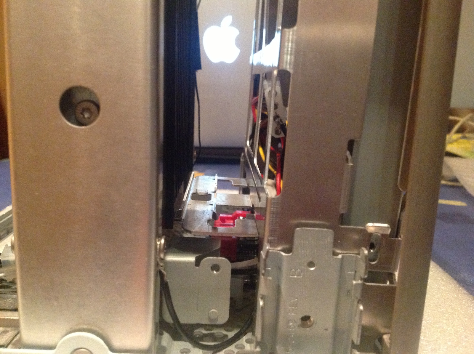
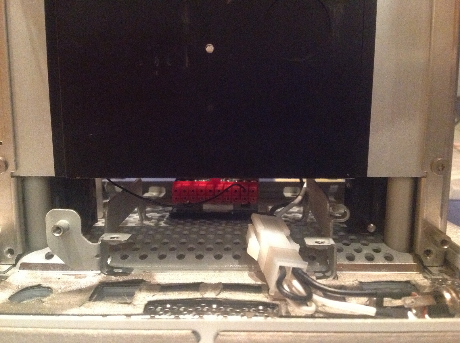
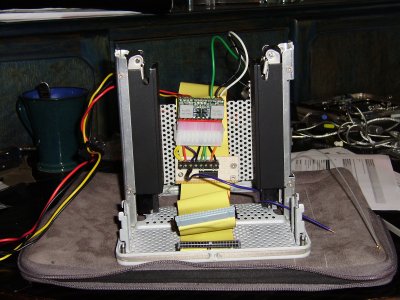

Pics

I' ll be uploading pics as the project evolves
http://www.tonymacx86.com/members/icubefan/albums/uncut-g4-cube-mod/
to be continued...
 
About the motherboad:

Despite being slightly underpowered ( only 1.8 ghz i3 CPU) the NUC mobo is the ideal choice for this project for obvious reasons.
55692-original-cube-motherboard-versus-nuc-motherboard.JPG

I chose the Thunderbolt version over the Ethernet/dual HDMI one for the sake of future expandability.
I made a small mistake though, the barebones version doesn' t have an internal USB header so I 'm stuck with only three USB ports. An internal powered USB Hub will be needed.

Another caveat is the lack of a 5V Standby line, needed for the original power switch.

Pros.

-4" x 4" size
-Low power consumption (27-28 Watts at full load)
-Thunderbolt port
-mSATA


Cons.

-Only 3 USB 2.0 ports
-No custom solution header ( no 3.3 V, 5VSB pins)
-CPU not upgradable
 
Last edited by a moderator:
This looks very interesting. Certainly a diversion from the Cube builds to date. I'll be watching as it progresses!

One question. Is it your intention to fab some sort of internal panel and attach the female ends (HDMI, USB, DC) to it or simply route the cables through the bottom and connect up under the Cube?

Nice work!


Ersterhernd
 
One question. Is it your intention to fab some sort of internal panel and attach the female ends (HDMI, USB, DC) to it or simply route the cables through the bottom and connect up under the Cube?


Ersterhernd

Hi Ersterhernd

The idea is to have an internal panel to attach the female ends.
I'm still undecided on what material to use ( pvc , plexi, aluminium?) and how to attach the female ends to the panel (glue?)

Suggestions are welcome !:D

iCubeFan
p.s.: I 've read your first i3 Cube build topic a thousand times !
 
About the power switch

55949-connections.JPG

Sources:

Cube Switch Modding
G4 Cube with Z77n-wifi,i3 3225

The original power switch was a must in my Cube build and one of the first challenges I had to face.
55948-original-power-switch-2.JPG55947-original-power-switch-1.JPG

The power switch needs the following connections to work (using minihack's simple method)

55527-original-g4-cube-power-switch-pinout.jpg

-a 5V standby line
-an earth connection
-a connection to the mobo front header power pins. (+ & -)


As I mentioned earlier the NUC motherboard doesn't have an available 5V standby line so I needed a way to provide this voltage to the power switch.

The solution was to use an additional psu that would provide the necessary 5VSB.The picopsu was the best choice, it's incredibly small and I'm planning more ways of using it in this build.

55945-picopsu.JPG


Please note the following:

-the picopsu needs to accept a wide input voltage range (12-25 V), the NUC uses a 19V External power supply laptop type.
-the picopsu doesn't need to be powered on for the cube switch to work.

One more thing was needed: a two male to female DC cable to power both the pico and the mobo with one power brick.
I searched online but didn't find anything like that so I had to build my own.

55944-dc-splitter.JPG55946-dc-splitter-connected-picopsu-mobo.JPG

It's also important to mention that the switch plate needs a ground connection.

I used a black molex cable connected to the Cube metal cage as shown in the below picture ( the picture belongs to a test build )

55696-testing-picopsu-original-power-switch.jpg

In the final build the picopsu will be placed in the space between the original HDD and the optical drive.

more updates soon
 
Last edited by a moderator:
Power Switch update & other stuff

So I finally found the right location for the picopsu , the space between the HDD and the optical drive.

I used velcro to fix it to the case.

56232-picopsu-final-location-2.JPG


With the picopsu in the right place I could also complete the power switch mod.

I shortened the mobo power connector as much as possible.

56507-modded-power-switch.JPG


Changed the location of the switch plate earth connection.

56505-switch-plate-ground.JPG


and used a longer wire for the 5VSB connection.

56506-picopsu-5vsb-connection.JPG


I'm still waiting for the copper heat spreader that I ordered. As soon as I have it I will be able to move to the next step: how to secure the motherboard .
56510-d1nu-impatics-copper-heat-spreader.jpg

I have also found a nice USB powered slot load BR optical drive.

http://store.mcetech.com/Merchant2/merchant.mvc?Screen=PROD&Product_Code=BD6XSLU2

The cool thing is that it should fit perfectly in the original optical drive spot ( width & depth are almost the same but it's 1 centimeter shorter) so I wouldn't need to gut the original optical drive case.

I'm also considering several options to expand the 3 existing USB 2.0 ports.

This powered hub seems ideal as it's small enough to be fitted between the HDD cage & the Optical Drive.

http://www.newegg.com/Product/Product.aspx?Item=N82E16817111402

Question to the electronics wizards that may read this. Can I plug this hub (or any other USB powered hub) to an available 5V pin in my motherboard by using a custom cable ?
 
Last edited by a moderator:
Question to the electronics wizards that may read this. Can I plug this hub (or any other USB powered hub) to an available 5V pin in my motherboard by using a custom cable ?
I wouldn't advise it unless you are certain of what will be connected to the Hub. The issue is that the hub has 7 usb ports, so if you plugged in 7 devices that used the full 0.5A, that adds up to 3.5A. Most header plugs are not designed to to provide this much current, and you may end up burning out something on the motherboard.

If you know what will be plugged into the hub, and know (or can measure) how much current will be drawn by all of these device, and can find a pin on the motherboard that is rated for this power then you will be fine. Otherwise I would be careful.
 
What Kiwi says is true. Don't do that, it will destroy the 5v supply of the USB Port.

Will you cut off a part of the original MOBO and reuse its connectors?
 
For the hub, why not use the power from the pico? You can make a simple circuit to get it to power on when the NUC comes on - e.g. use the a 5v signal from the NUC to trigger a reed switch that connects the green power on wire terminal to ground - then you can use the Pico to power the hub.
Seems a shame to have bought the extra power supply and then only to use it for the standby voltage, so use it as a resource in your build.
When I did my mini in a Cube mod I used the Pico in exactly that way. I used a cut down female ATX extension plug to run the wires I wanted from the pico to a small PCB (vero board) on which I had the little electronic reed switch and a few connections to give me extra 5v, 12v and 3.3v power. This also was easy to fit in exactly the gap where you have placed your pico.
PS Ignore the long IDE cable in the picture (back in the day I used that on an early Mac Mini to turn a single IDE DVD drive connection into a master slave connection for running both a DVD drive and a full size 3.5" HD).

EDIT:

For an example circuit to turn on the PicoPSU see second attachment and then look at this link which shows suitable simple cheap reed relay switch :
http://www.maplin.co.uk/dil-reed-relay-2613#specification
 

Attachments

  • P2240009.JPG
    P2240009.JPG
    955.9 KB · Views: 2,258
  • circuit.jpg
    circuit.jpg
    46.4 KB · Views: 917
Status
Not open for further replies.
Back
Top