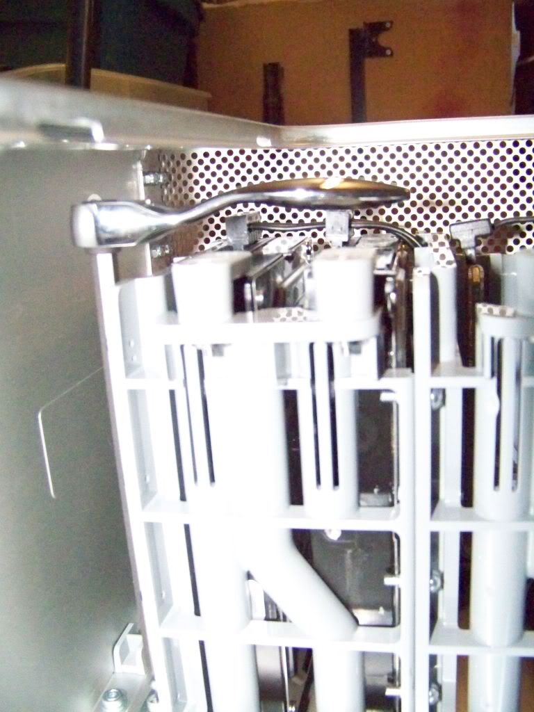
Back in post #20 of this thread I was trying to figure out how I would get access to the two bottom screws that are used to mount the drive cage to the aluminum rails. I thought that I would have to drill two access holes in the front lip and buy a really long screw driver to get at them. I wound up getting a 6" screwdriver bit and using a mini bit ratchet that I had in my tool box. It fit perfectly and works like a charm.
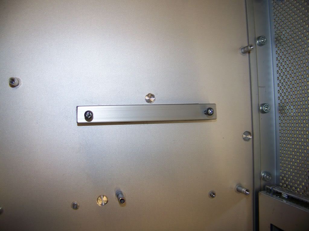
By masking the area around the aluminum bars and removing the masking tape at about the 6 hour mark, I am able to create a really clean JB Weld. Here is the lower drive cage mounting rail with minimal seepage.
and the upper drive cage mounting rail...minimal glue seepage.
Soldering the Drive Pigtail
Well after all the work I put into my homemade drive cage and fancy pigtail wiring, today I cut it all off. What I am left with is two stubby SATA power pigtails from the PSU.
I salvaged the drive power pigtail connector from the original G5 PSU and I'm going to connect it to the stubby power pigtails of the PSU. This way I can re-use the original black power cable harness from the G5 that runs underneath the motherboard and powers the optical and hard drives.
Soldered together
Sleaved
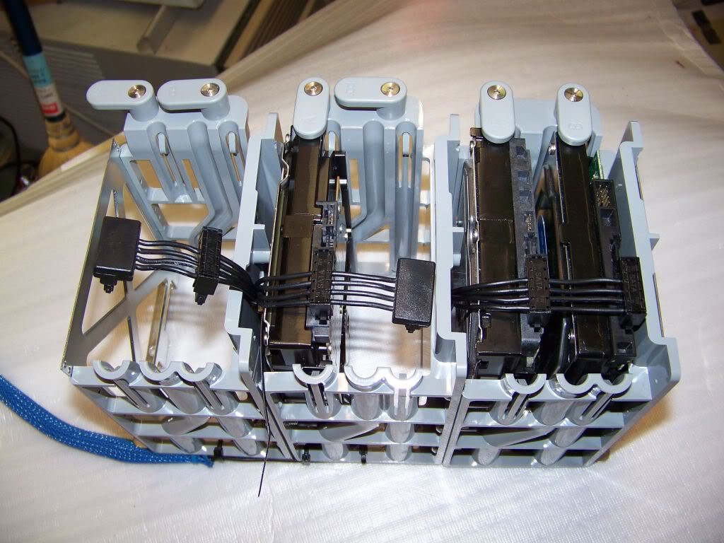
Wiring the Drive Cage
I carefully removed the SATA power connectors from the ends of the clipped off power pigtails and installed them inline so that each wire will now power two drives. Since each of the original pigtails could power three devices, this should be fine.
Completed - underneath. Wires are neatly zap-strapped to the back of the cage to minimize unsightly wires.
Completed - Front. I had to replace the MOLEX connector that used to feed power to the original G5 optical drive. I replaced it with two SATA connectors.
I plan to add some cool lighting to the top and bottom of the case. This blue cold cathode kit comes with two cathode bars, a switch for the back panel, a circuit box and a power connector. Installation uses velcro. I may or may not use it.
I added blue sleeving to all the wires.
ASSEMBLY
The first thing to be installed is the top shelf and power supply. This photo was taken with the G5 case upside-down as it was easier to install the top shelf that way. The door latching mechanism is much simpler to install than it is to remove.
This isn't a really good picture of how I am routing the wire for the top cathode. The cathode itself is mounted behind the top lip, just in front of the power supply.
The cathode is lying just in front of the power supply.
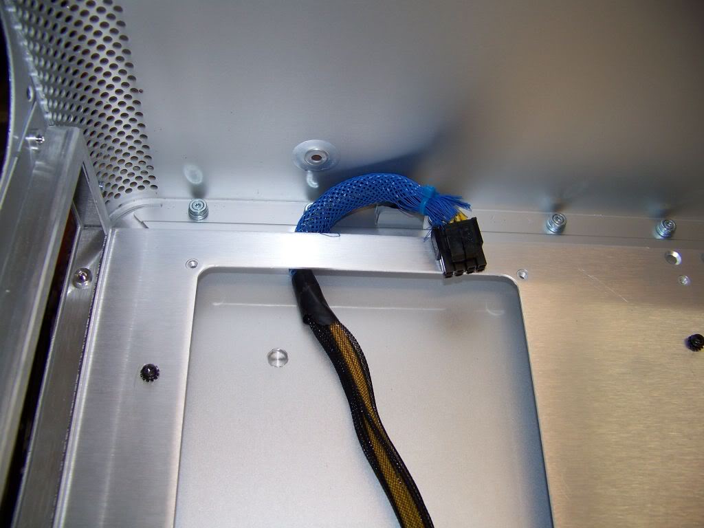
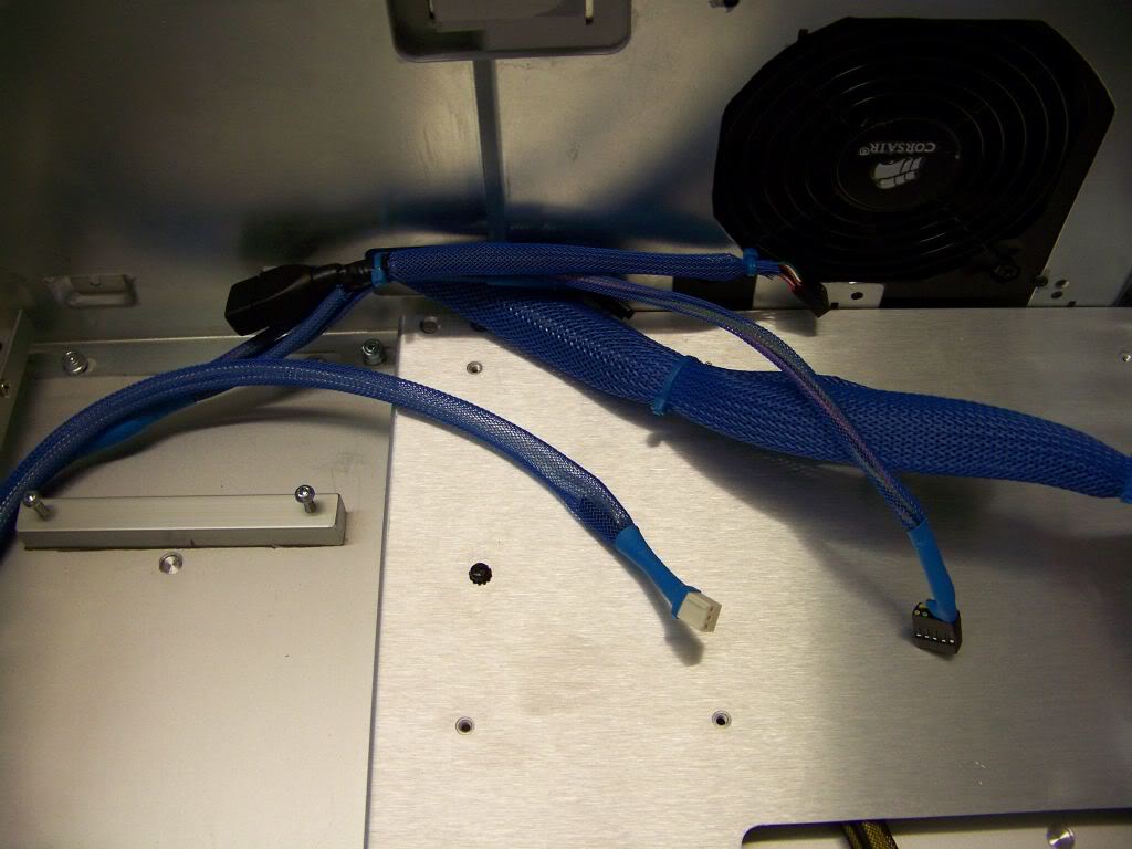
Time to install the motherboard tray. Here is the CPU power cable routed nicely under the tray.
Front Fans and Front Panel cable installed.
This photo shows the routing the front panel cable and the front fans power cable.
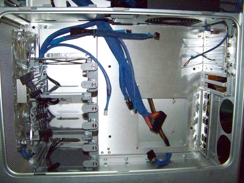
Its starting to look like something!
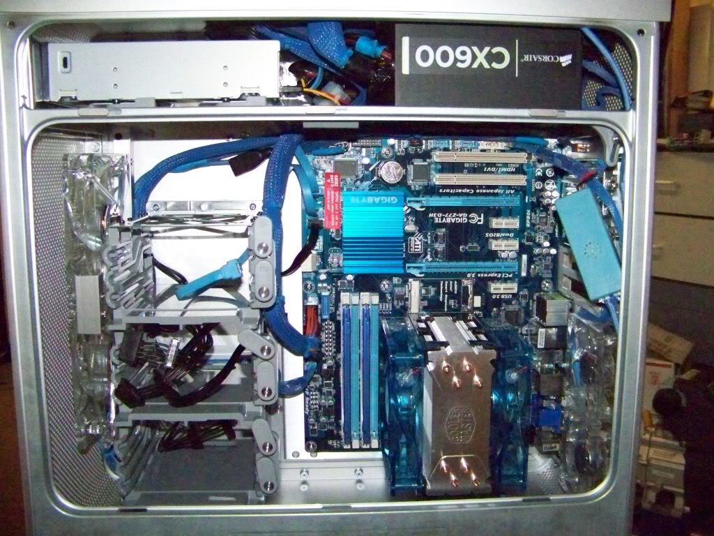
The motherboard tray is now installed....cabling starting to build up.
Thats all for today! Almost time to prepare the motherboard for installation.