Contribute
Register

[SUCCESS] Gigabyte Designare Z390 (Thunderbolt 3) + i7-9700K + AMD RX 580

I appreciate your work. And one question..

Preparation of Card:
  • If motherboard contains a compatible 5-pin Thunderbolt header (THB_C), connect the GC-Titan Ridge to motherboard with a Thunderbolt header cable that is supplied with the GC-Titan Ridge.
  • If motherboard does not contain a Thunderbolt header, connect pins 1 and 3 with a simple female/female breadboard jumper wire, as follows:
    • Hold the GC-Titan Ridge vertically so the PCIe pins are pointing down to the floor.
    • On the back of the card, locate the 5-pin vertical header (J1).
    • Pin 1 is the top pin
    • Pin 3 is the middle pin
    • Connect the top pin and middle pin

Does this procedure (connecting pins) only apply to 'titan ridge'? Can I apply to 'alpine ridge' or 'asus thunderboltex'?
 
Thanks @CaseySJ - please see attached.
Please try the attached config.plist (backup the existing one and copy serial number, MLB, and system UUID into the new one before using).

At the OpenCore Picker, perform a Reset NVRAM on the first boot with the new config.plist. When the system restarts, boot normally into Catalina.

It is also possible that OpenCore does not like the Western Digital SN750...
 

Attachments

  • config.plist
    21.2 KB · Views: 46
I extracted the Thunderbolt ROM with SPI programmer as tbdump.rom and flash it with SPI with tbmod.rom. I modify the rom both myself and with ThunderboltUtil but neither work.
Hello @shiecldk,

Attached file Alienware-M15-TB3-Firmware.zip contains two versions of the modified firmware, called MOD-1 and MOD-2. Please try MOD-1 first and see what works and what does not. Then try MOD-2 only if necessary.

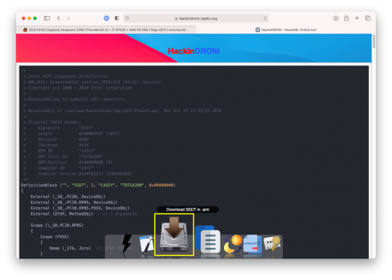
It is also necessary to use a Thunderbolt SSDT. This can be done by following the procedure below using the wonderful HackinDROM by @Inqnuam:
HackinDROM-1.pngScreen Shot 2020-10-19 at 11.55.20 AM.pngHackinDROM-2.png
When the SSDT is downloaded (it will appear in the Downloads folder) copy it to your CLOVER/ACPI/Patched or OpenCore OC/ACPI folder. Also copy the attached SSDT-DTPG.aml into the same folder.

If using OpenCore, be sure to add both SSDT references into config.plist. Then perform a cold boot (shutdown the system and flip power switch on PSU to OFF for 10 seconds).

The SSDT is already configured for PEG1.

Do not use SSDT-10-TbtOnPch.aml.
 

Attachments

  • SSDT-DTPG.aml
    800 bytes · Views: 42
  • Alienware-M15-TB3-Firmware.zip
    217.8 KB · Views: 48
Hello @shiecldk,

Attached file Alienware-M15-TB3-Firmware.zip contains two versions of the modified firmware, called MOD-1 and MOD-2. Please try MOD-1 first and see what works and what does not. Then try MOD-2 only if necessary.

It is also necessary to use a Thunderbolt SSDT. This can be done by following the procedure below using the wonderful HackinDROM by @Inqnuam:
View attachment 492409View attachment 492411View attachment 492410
When the SSDT is downloaded (it will appear in the Downloads folder) copy it to your CLOVER/ACPI/Patched or OpenCore OC/ACPI folder. Also copy the attached SSDT-DTPG.aml into the same folder.

If using OpenCore, be sure to add both SSDT references into config.plist. Then perform a cold boot (shutdown the system and flip power switch on PSU to OFF for 10 seconds).

The SSDT is already configured for PEG1.

Do not use SSDT-10-TbtOnPch.aml.
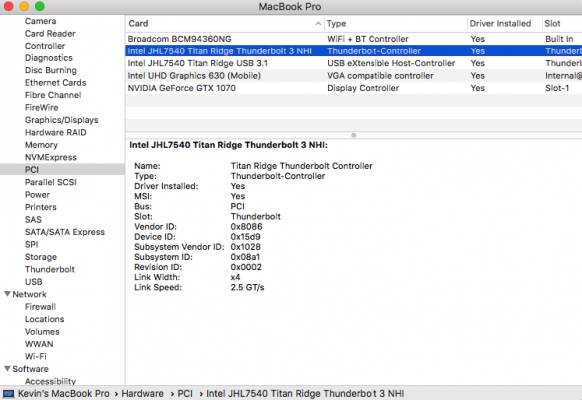
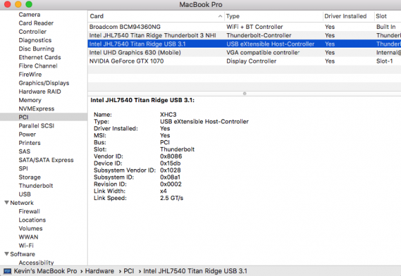
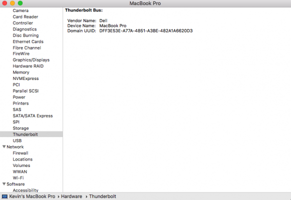
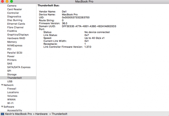
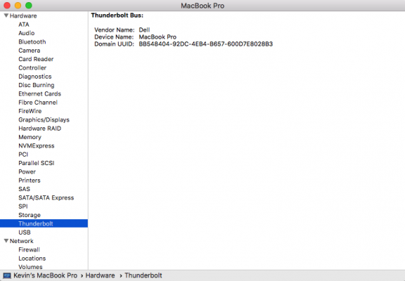
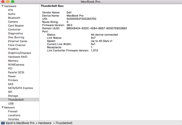
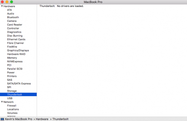
Hi @CaseySJ , thanks for the help! Both the MOD-1 and MOD-2 get thunderbolt bus detected in System Information just like real mac. However, my egpu is no longer working with both roms. The egpu thunderbolt device is detected by ioreg; however, nothing shows in PCI in System Information using either hotplug, cold boot, etc. The hotplug works with both roms but egpu is not working. I'm use a 750 Ti with High Serria. It worked before I flashed these roms. Also, when the egpu thunderbolt device is connected, the bus infomation has some problems in System Information.app. The Port info disappears. I'll attach some files and pictures in the next post.
 
Last edited:
Hi @CaseySJ , thanks for the help! Both the MOD-1 and MOD-2 get thunderbolt bus detected in System Information just like real mac. However, my egpu is no longer working with both roms. The egpu thunderbolt device is detected by ioreg; however, nothing shows in PCI in System Information using either hotplug, cold boot, etc. The hotplug works with both roms but egpu is not working. I'm use a 750 Ti with High Serria. It worked before I flashed these roms. Also, when the egpu thunderbolt device is connected, the bus infomation has some problems in System Information.app. The Port info disappears. I'll attach some files and pictures in the next post.
I somewhat suspected this because it's not immediately clear where Thunderbolt Switch resides. From @joevt's ThunderboltUtil, we see that Thunderbolt Switch might be on Port 3 or 4 or 5 or 8. In the DROM I created for the Alienware M15, I chose Port 5. Now that Thunderbolt Bus is enabled, please post the IOReg file (IORegistryExplorer --> File --> Save As...) so we can find the correct port.
Code:
% source ThunderboltUtil.sh
% loadfwfile tbdump.rom
% usedromnum 1

% dumpdrom
0x01) UID: 0x00D4000000000000
0x0d) Device ROM Revision: 1
0x10) Vendor ID: 0xD4
0x12) Device ID: 0x8A1
0x14) Device Revision: 0x1
0x15) EEPROM Revision: 36
0x16)   1: 800280000000
0x1e)   2: 900180000000
0x26) - 3:
0x28) - 4:
0x2a) - 5:
0x2c)   6: 200100640000000000
0x37)   7: 80
0x3a) - 8:
0x3c)   9: 500000
0x41)   A: 500000
0x46) - B:
0x48)   1: "Dell"
0x4f)   2: "Alienware M15"
0x5f) End
 
Last edited:
I appreciate your work. And one question..


Does this procedure (connecting pins) only apply to 'titan ridge'? Can I apply to 'alpine ridge' or 'asus thunderboltex'?
This procedure actually depends on the SPI ROM chip used on the card. Most Alpine Ridge and Titan Ridge cards use either:
  • Winbond 25Q80DV (or similar)
  • Macronix MX25L8006E (or similar)
Both of these use the same pin layout (25-series SPI Flash), hence the procedure is compatible with both of these chip families.

UPDATE: I misunderstood the question. You are asking about connecting a jumper to the J1 header of the GC-Titan Ridge or GC-Alpine Ridge to force-enable the card. In that case the procedure applies only to Gigabyte's GC-Titan Ridge and (maybe) to GC-Alpine Ridge. Other cards such as Asus ThunderboltEX 3 require some other technique (it would be best to use those cards on a motherboard that has a compatible Thunderbolt header).
 
Last edited:
I somewhat suspected this because it's not immediately clear where Thunderbolt Switch resides. From @joevt's ThunderboltUtil, we see that Thunderbolt Switch might be on Port 3 or 4 or 5 or 8. In the DROM I created for the Alienware M15, I chose Port 5. Now that Thunderbolt Bus is enabled, please post the IOReg file (IORegistryExplorer --> File --> Save As...) so we can find the correct port.
Code:
% source ThunderboltUtil.sh
% loadfwfile tbdump.rom
% usedromnum 1

% dumpdrom
0x01) UID: 0x00D4000000000000
0x0d) Device ROM Revision: 1
0x10) Vendor ID: 0xD4
0x12) Device ID: 0x8A1
0x14) Device Revision: 0x1
0x15) EEPROM Revision: 36
0x16)   1: 800280000000
0x1e)   2: 900180000000
0x26) - 3:
0x28) - 4:
0x2a) - 5:
0x2c)   6: 200100640000000000
0x37)   7: 80
0x3a) - 8:
0x3c)   9: 500000
0x41)   A: 500000
0x46) - B:
0x48)   1: "Dell"
0x4f)   2: "Alienware M15"
0x5f) End
Do you think it's because this is a Alpine Ridge chip? I saw the SSDT is showing Titan Ridge so am not sure if it has something to do with this. I attached the ioreg for the both mod roms when tb egpu is connected. USB-C with hotplug seems to work with both roms.

Both roms shows the following info when tb egpu is connected/disconnected:
mod2_pci1.png
mod2_pci2.png

For mod1:

when egu is connnected:
mod1_2.png

when egu is disconnnected:
mod1_2.png


For mod2:

when egu is connnected:
mod2_1.png

when egu is disconnnected:
mod2_2.png
 

Attachments

  • tb_mod1.ioreg
    34.5 MB · Views: 44
  • tb_mod2.ioreg
    34.5 MB · Views: 48
  • mod1_1.png
    mod1_1.png
    61.8 KB · Views: 51
Last edited:
Do you think it's because this is a Alpine Ridge chip? I saw the SSDT is showing Titan Ridge so am not sure if it has something to do with this. I attached the ioreg for the both mod roms when tb egpu is connected. USB-C with hotplug seems to work with both roms.

Both roms shows the following info when tb egpu is connected/disconnected:
...
Some observations:
  • Thunderbolt Switch is indeed on Port 5, and it is activated, so that's good.
    Screen Shot 2020-10-19 at 5.12.32 PM.png

  • Looks like MOD-1 is better than MOD-2, so MOD-2 should not be used. Attached is MOD-3 to try next. This one is a bit more experimental.
 

Attachments

  • tbdump-CASEYSJ-MOD-3.rom.zip
    108.9 KB · Views: 45
Some observations:
  • Thunderbolt Switch is indeed on Port 5, and it is activated, so that's good. View attachment 492454
  • Looks like MOD-1 is better than MOD-2, so MOD-2 should not be used. Attached is MOD-3 to try next. This one is a bit more experimental.
It gives the same result. Wonder what you changed for this one. Also, is it possible that we have to activate more switches?

when egu is connnected:
mod3_1.png
when egu is disconnnected:
mod3_2.png
 

Attachments

  • tb_mod3.ioreg
    34.4 MB · Views: 43
@CaseySJ This is the ioreg with the original unmod rom. I am guessing the port might be wrong? Can we try port 3? Also, how did you modify the rom. I checked with hex, it seems they're different from this guide.
dump.png

dump2.png
 

Attachments

  • tbdump.ioreg
    34.7 MB · Views: 45
Back
Top