Contribute
Register

[SUCCESS] Gigabyte Designare Z390 (Thunderbolt 3) + i7-9700K + AMD RX 580

  • Only a simplified Ssdt TbtonPCH (without preconfiguration methods ICMS/CNHI and stay with boot register values for RP18,...NH10
  • I had this 0xE00002eb error before firmware modification resulting on self disconnecting after around 20s. Now it is not prefect, i dont have 0x101 for normal results but always 0x7 with no device connected and 0x2 when connected. I suppose that is related to XHC2 not visible at boot or something else
  • I will send u my current SSDT and modified firmware if you want to post it ( it include DROM from iMac19,1).. We still have to understand CRC32/CRC8 on TbtDROM to custom each firmware ( UUID and if we want the device name)
Just FYI...last night I modified TbtOnPch as follows:
  • Created method to display Link Status of all 4 ports. Why 4 ports? Because that's what latest Linux kernel does. The ports are numbered 1, 2, 3, 4.
  • Connected only one TB3 device at a time.
  • This SSDT sets P2TR mailbox register to 0x05.
  • Hot plug does not work.
  • Test 1: Connect TB device to top port.
    • Result:
      • Port 1: 0x02 Device Connected (top port)
      • Port 2: 0x07 No device connected
      • Port 3: 0x07 No device connected
      • Port 4: 0x07 No device connected
      • In IOReg, we see device connected to DSB1.
  • Test 2: Connect TB device to bottom port.
    • Resut:
      • Port 1: 0x07 No device connected
      • Port 2: 0x07 No device connected
      • Port 3: 0x02 Device Connected (bottom port)
      • Port 4: 0x07 No device connected
      • In IOReg, we see device connected to DSB1. (It still shows up under DSB1 instead of DSB4.)
This suggests that each physical Thunderbolt 3 port has two logical port numbers.
  • The first physical port gets logical port numbers 1 and 2.
  • The second port gets logical port numbers 3 and 4.
  • Even though the device is properly detected on the right port, it attaches only to DSB1 regardless of the physical port.
However, if we set P2TR mailbox register to 0x0D (the standard case):
  • Hotplug works.
  • TNODE/TBUS do not always show up, but they will show up under some circumstances.
  • Port link state is the same as before:
    • Logical ports 1 and 2 belong to Physical Port 1.
    • Logical ports 3 and 4 belong to Physical Port 2.
  • And IOReg is correct:
    • TB3 device in Port 1 --> attaches to DSB1.
    • TB3 device in Port 2 --> attaches to DSB4.
In both cases, however, Link State shown in System Information --> Thunderbolt is always 0xe00002eb.

Based on this, I decided to check something else:
  • I switched back to P2TR = 0x05 so that TNODE/TBUS will always appear.
  • After ICMS(), I reset all 4 logical ports (because Linux kernel also does this) by issuing special commands to CRMW(). The commands are:
    • Disable all ports first:
      • CRMW (0x37, 1, 1, 0x00004000, 0x00004000) // disable port 1
      • CRMW (0x37, 2, 1, 0x00004000, 0x00004000) // disable port 2
      • CRMW (0x37, 3, 1, 0x00004000, 0x00004000) // disable port 3
      • CRMW (0x37, 4, 1, 0x00004000, 0x00004000) // disable port 4
    • Re-enable all ports:
      • CRMW (0x37, 1, 1, 0x00004000, 0x00000000) // enable port 1
      • CRMW (0x37, 2, 1, 0x00004000, 0x00000000) // enable port 2
      • CRMW (0x37, 3, 1, 0x00004000, 0x00000000) // enable port 3
      • CRMW (0x37, 4, 1, 0x00004000, 0x00000000) // enable port 4
      • CRMW (0x37, 1, 1, 0x00000000, 0x00004000) // enable port 1
      • CRMW (0x37, 2, 1, 0x00000000, 0x00004000) // enable port 2
      • CRMW (0x37, 3, 1, 0x00000000, 0x00004000) // enable port 3
      • CRMW (0x37, 4, 1, 0x00000000, 0x00004000) // enable port 4
  • Result:
    • Link State for both Receptacle 1 and Receptacle 2 in System Information --> Thunderbolt changes:
      • From:
        • 0xe00002eb
      • To:
        • 0x101
    • Update 14 Mar 2020: Link State remains the same after resetting ports (0xe00002eb).
    • But no devices attach to the ports. Any device that was previously attached during boot gets disconnected.
      • I think this is due to some (small) problem with CTBT() or NHI0.PCED().
That's as far as I got last night.
 
Last edited:
Just FYI...last night I modified TbtOnPch as follows:
  • Created method to display Link Status of all 4 ports. Why 4 ports? Because that's what latest Linux kernel does. The ports are numbered 1, 2, 3, 4.
  • Connected only one TB3 device at a time.
  • This SSDT sets P2TR mailbox register to 0x05.
  • Hot plug does not work.
  • Test 1: Connect TB device to top port.
    • Result:
      • Port 1: 0x02 Device Connected (top port)
      • Port 2: 0x07 No device connected
      • Port 3: 0x07 No device connected
      • Port 4: 0x07 No device connected
      • In IOReg, we see device connected to DSB1.
  • Test 2: Connect TB device to bottom port.
    • Resut:
      • Port 1: 0x07 No device connected
      • Port 2: 0x07 No device connected
      • Port 3: 0x02 Device Connected (bottom port)
      • Port 4: 0x07 No device connected
      • In IOReg, we see device connected to DSB1. (It still shows up under DSB1 instead of DSB4.)
This suggests that each physical Thunderbolt 3 port has two logical port numbers.
  • The first physical port gets logical port numbers 1 and 2.
  • The second port gets logical port numbers 3 and 4.
  • Even though the device is properly detected on the right port, it attaches only to DSB1 regardless of the physical port.
However, if we set P2TR mailbox register to 0x0D (the standard case):
  • Hotplug works.
  • TNODE/TBUS do not always show up, but they will show up under some circumstances.
  • Port link state is the same as before:
    • Logical ports 1 and 2 belong to Physical Port 1.
    • Logical ports 3 and 4 belong to Physical Port 2.
  • And IOReg is correct:
    • TB3 device in Port 1 --> attaches to DSB1.
    • TB3 device in Port 2 --> attaches to DSB4.
In both cases, however, Link State shown in System Information --> Thunderbolt is always 0xe00002eb.

Based on this, I decided to check something else:
  • I switched back to P2TR = 0x05 so that TNODE/TBUS will always appear.
  • After ICMS(), I reset all 4 logical ports (because Linux kernel also does this) by issuing special commands to CRMW(). The commands are:
    • Disable all ports first:
      • CRMW (0x37, 1, 1, 0x00004000, 0x00004000) // disable port 1
      • CRMW (0x37, 2, 1, 0x00004000, 0x00004000) // disable port 2
      • CRMW (0x37, 3, 1, 0x00004000, 0x00004000) // disable port 3
      • CRMW (0x37, 4, 1, 0x00004000, 0x00004000) // disable port 4
    • Re-enable all ports:
      • CRMW (0x37, 1, 1, 0x00004000, 0x00000000) // enable port 1
      • CRMW (0x37, 2, 1, 0x00004000, 0x00000000) // enable port 2
      • CRMW (0x37, 3, 1, 0x00004000, 0x00000000) // enable port 3
      • CRMW (0x37, 4, 1, 0x00004000, 0x00000000) // enable port 4
  • Result:
    • Link State for both Receptacle 1 and Receptacle 2 in System Information --> Thunderbolt changes:
      • From:
        • 0xe00002eb
      • To:
        • 0x101
    • But no devices attach to the ports. Any device that was previously attached during boot gets disconnected.
      • I think this is due to some (small) problem with CTBT() or NHI0.PCED().
That's as far as I got last night.
I had same result with this damn error 0xe00002eb. You have done impressive research to find this register @ 0x37.

Have you another informations on others control/status registers to take full control of this controller ;) ?

I have use this CRMW method to read DROM base address on VSEC ID 01h and result is 0x210.. that is just right, we have DROM 0x4210 (with Tbt firmware beginning @ 0x4000).
I haven't found reading register and methodology (bit banging ?) to extract DROM from firmware and display it as property.

Capture d’écran 2020-03-13 à 16.15.19.png
 
Last edited:
I had same result with this damn error 0xe00002eb. You have done impressive research to find this register @ 0x37.

Have you another informations on others control/status registers to take full control of this controller ;) ?

I have use this CRMW method to read DROM base address on VSEC ID 01h and result is 0x210.. that is just right, we have DROM 0x4210 (with Tbt firmware beginning @ 0x4000).
I haven't found reading register and methodology (bit banging ?) to extract DROM from firmware and display it as property.

Because latest Linux kernel includes both Titan Ridge and USB4 support, I've been examining the Thunderbolt driver code located in the drivers/thunderbolt directory. The most interesting file so far is icm.c and a number of header files (xxx.h).
  • Information about CIO register 0x37 comes from examining the function icm_reset_phy_port().
  • Information about allowing all devices to connect comes from examining the function icm_firmware_init().
  • Linux source code can be downloaded from here by clicking the green Clone or Download button.
The Linux code is providing many good insights into the meaning of each register and the meanings of return values. But it is still somewhat limited. It doesn't provide complete documentation of Thunderbolt control registers.

Screen Shot 2020-03-13 at 8.24.13 AM.png
 
Hello @CaseySJ, I downloaded the script made by @byteminer but it doesn't work, i think I don't do right things; I put the new script in "run a shell" and clone my ssd. After the operation being completed, I run the terminal with
"cd /System/Volumes/Data/Users/Shared
tail -f EFIClone.log"
But I have a bad result (the EFI file is in my downloads). I put the screenshot in attached files... In his little tutorial byteminer explains that we must write LOG_FILE="/Users/Shared/EFIClone.log I don't understand where and when during the operation. Does it replace your path ? Thanks a lot
Hello @mazop89,

In Terminal, we must run these as two separate commands:
Code:
cd /Users/Shared
Code:
more EFIClone.log
Note that cd /Users/Shared is the same as [/icode]cd /System/Volumes/Data/Users/Shared[/icode]. Please check if EFIClone.log exists in the /Users/Shared folder. If so, please compress and upload.
 
@CaseySJ this is what am getting with SSDT I got from you very similar to what I was getting before.
Hot plug definitely don't work
Hello @galisrule,

Have you connected the Thunderbolt header cable from GC-Titan Ridge to your motherboard?
 
I just updated to Catalina. It it safe to enable FileVault?
Although I have no experience with FileVault, I believe it is okay to use.

Please see @pastrychef's build guides for more information:
  • Guide 1 -- Asus ROG Strix Z370-G Gaming
  • Guide 2 -- Gigabyte Z390M Gaming
 
@CaseySJ yes indeed thunderbolt header cable is connected
 
@CaseySJ yes indeed thunderbolt header cable is connected
Couple of suggestions:
  • Have you tried the other way -- by disconnecting the header cable and attaching a jumper between pins 3 and 5 of the J1 header on the GC-Titan Ridge card itself?
  • Have you tried booting with a Thunderbolt 3 device (not USB-C) already connected to Port #1? Then do you get hot-plug capability?
Currently we're seeing some strange behavior when connecting Thunderbolt devices to Port #2. So it's better to perform all initial testing with Port #1.
 
been following this thread a lot and I will do as you say I will definitely try your suggestions
 
** Thunderbolt Bus/Local Node Interim Update **

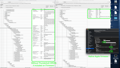
@Elias64Fr has modified the native Thunderbolt firmware on the Designare Z390 -- similar to the DSM2 modified firmware for GC-Titan Ridge! Most of the core functionality is operational, but some final issues remain with XHC (USB) controller.

Preface:
  • Initially we wanted to avoid flashing/modifying the Designare Z390 Thunderbolt firmware because:
    • The MXIC Flash ROM chip was proving very difficult / impossible to read and write reliably.
    • The procedure is more invasive and risky than simply installing a SSDT.
  • However, after many weeks of effort, it seems that modifying the firmware may be the best option for the near term.
  • There is just not enough publicly available information about Titan Ridge control registers (at this time) to create a fully operational SSDT.
  • @Elias64Fr found a reliable way to read and write to the Designare Z390 SPI Flash ROM.
Plan:
  • Because I have a Designare Z390 Test Bench, I'll flash and test modified Thunderbolt firmware over the weekend.
  • Will report detailed findings and issues.
  • Will ask a handful of volunteers to test the modified firmware once it's ready for beta testing.
    • Volunteers should have either Raspberry Pi Model 3B or 4, or CH341a Programmer.
    • Volunteers should have prior experience with flashing SPI ROM chips.
    • Volunteers should understand the risks.
    • Volunteers should not touch a mission critical system. If they use their Designare Hackintosh for professional purposes, they should not touch that system.
SPI ROM Flashing Guides:
Capture d’écran 2020-03-13 à 13.21.42.png Capture d’écran 2020-03-13 à 13.38.16.png
 
Last edited:
Back
Top