Contribute
Register

[SUCCESS] Gigabyte Designare Z390 (Thunderbolt 3) + i7-9700K + AMD RX 580

Can you please share your ThunderboltConfig and SSDT? If you're getting a Titan Ridge to work normally, all of us would be extremely interested to see how you did it.

EDIT:
  • Maybe I misunderstood. Are you using a flashed GC-Titan Ridge or it still has the original firmware?

To me it looks like he use a flashed Titan Ridge. (Thunderbolt Entry present)

But would also be interested in the ssdt.

Could you share it with us please? @juantrix
 
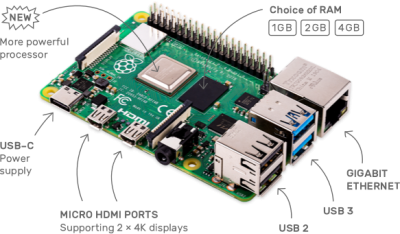
A set of jumper wires was just delivered so I plan to try the Raspberry Pi 4. It has only two 3.3V power pins, but I believe we need 3:
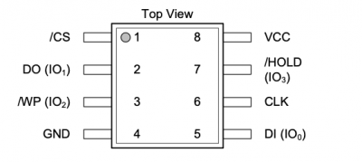
  • /WP (pin 3 on chip)
  • /HOLD (pin 7 on chip)
  • VCC (pin 8 on chip)
So I'll have to jerry rig a Y-splitter.

Raspberry Pi's SPI pins should already provide a 3.3V bias on:
  • MOSI (pin 19 on RPi) --> DI (pin 5 on chip)
  • MISO (pin 21 on RPi) --> DO (pin 2 on chip)
  • SCLK (pin 23 on RPi) --> CLK (pin 6 on chip)
  • CE0 (pin 24 on RPi) --> /CS (pin 1 on chip)

I do not have one so I think that the best choice would be to buy the:


The only difference is I could go get it now.
 
I do not have one so I think that the best choice would be to buy the:


The only difference is I could go get it now.
I tried the RPi last night with a (badly) doctored set of wires and flashrom couldn't detect the chip. So I would not recommend buying a RPi right away. Let me see if I get better results this evening...
 
** Mini-Guide for Flashing SPI ROM Chips using Raspberry Pi 3B or 4 **
Please do not quote the entire mini-guide. Post a link instead.

19 Dec 2021:
Warning!
Thunderbolt 4 Docks will not connect to flashed Thunderbolt 3 controllers.


pi4-labelled-99c2e8935bb3cfdb27d23f634ea98a7e.png

Most CH341A Programmers output a potentially dangerous 5V on the SPI (Serial Peripheral Interface) I/O pins (MOSI, MISO, SCLK). While some users have been successful with these low-cost programmers, more reliable alternatives are the Raspberry Pi Models 3B and 4. These devices contain 40 GPIO pins (General Purpose I/O) where certain pins are reserved for specialized functions including communicating with SPI devices. This allows the Raspberry Pi to function as an effective SPI Flash ROM reader/writer. Moreover, the SPI I/O pins are all biased at 3.3V and can accommodate chips such as Winbond W25Q80DV that operate at a voltage between 2.7V and 3.6V.

Disclaimer:
  • The procedure described here can brick / damage the device being modified.
  • You assume all risk and liability for carrying out any of the steps listed here.
  • You further understand that the steps listed here may or may not be accurate or applicable to your particular components.

Step 1: Parts Needed
  • Raspberry Pi kit with SD Card, heat sinks, power supply, and HDMI cable. Most Raspberry Pi kits contain all of these items.
  • Jumper wires such as this pack consisting of M/M, M/F, and F/F.
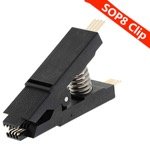
  • SOIC8 clip such as:
  • Update 7-Apr-2020:
    • For the Designare Z390, Z390 Aorus Xtreme, and other boards using a Winbond W25Q80DV, I now recommend the low-cost clip because it provides a better grip on these boards.
      51nle6XHrdL._SL1000__resize.jpg

Step 2: Procedure for Installing / Configuring Raspberry Pi
  1. Most Raspberry Pi kits come with a Micro SD Card and SD Card adapter. On the Mac, download Raspbian Buster with desktop and recommended software from here.
  2. Download and install Balena Etcher on the Mac.
  3. Insert Micro SD Card into the Mac (via the USB SD Card adapter) and burn the Raspbian Buster image to the Micro SD Card with Balena Etcher. When it's done, the Micro SD Card will have Linux ext4 file format, which is unrecognized on Mac. So just pull the card out.
  4. Remove Micro SD Card from the adapter and insert into Raspberry Pi and boot. Everything is already set up in the Micro SD Card for truly painless installation.
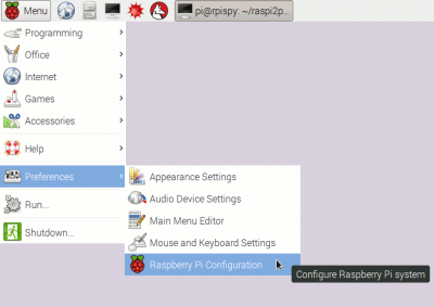
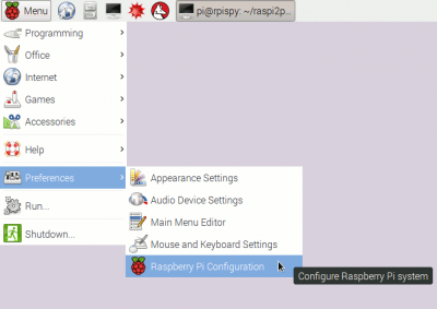
  5. Click the top left "Raspberry" icon, and select Raspberry Pi Configuration as shown:
    raspberry_pi_configuration.png
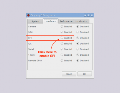
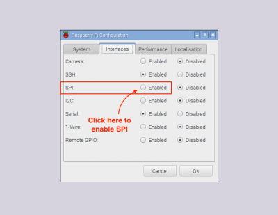
  6. Then select the Interfaces tab and click Enabled next to SPI (Serial Peripheral Interface) as shown:
    menucfg.png
  7. Reboot.
  8. Now you're ready to proceed.
However, turn off the Raspberry Pi:
  • When connecting wires to the GPIO pins.
  • When connecting SOIC8 Clip to the GC-Titan Ridge.

Step 3: Connect Pins from Raspberry Pi to SOIC8 Clip.
  • Turn OFF the Raspberry Pi and attach wires between Raspberry Pi and SOIC8 Clip as listed below and shown in the diagram.
  • May 2020 Update: The Supplemental Procedure is highly recommended. If you follow that procedure then it is not necessary to split the wire from Pin 17 into a "Y". Instead, follow the pin diagram below, but connect the first 3V3 Power pin (Pin 1 on Pi) to Pin 7 on the SOIC clip and connect the second 3V3 Power pin (Pin 17 on Pi) to Pin 3 on the SOIC clip.
Screen Shot 2020-03-10 at 3.03.34 PM.png

GPIO-Pinout-Diagram-2-markup.png Screen Shot 2020-03-02 at 9.04.25 AM.png
Step 4: Connect SOIC8 Clip to SPI Flash ROM
  • With Raspberry Pi turned off, gently connect the SOIC8 clip to the Flash ROM device.
  • If you're flashing the GC-Titan Ridge, connect the SOIC8 clip to the Winbond chip with the blue dot only. Do not modify the chip with the green dot.
  • Always squeeze and unsqueezed the spring-loaded SOIC8 clip gently. You do not want to scrape, dent, or damage the pins of the SPI Flash ROM.
  • Now power on the Raspberry Pi.

Step 5: Use flashrom to read and create backup of the original contents of the SPI Flash chip.
  • Lauch the Linux Terminal and use the commands below.
  • First we read the existing contents of the SPI Flash ROM and save it. It is critical to make this backup!
  • We read the contents three times and compare their checksums to ensure that all three files are identical. This ensures that the chip was read successfully.
  • The syntax for the read function is as follows (the spispeed parameter is essential):
sudo flashrom -p linux_spi:dev=/dev/spidev0.0,spispeed=1024 -r test1.bin

Code:
pi@raspberrypi:~/Documents $ sudo flashrom -p linux_spi:dev=/dev/spidev0.0,spispeed=1024 -r Backup1.bin
flashrom  on Linux 4.19.97-v7l+ (armv7l)
flashrom is free software, get the source code at https://flashrom.org

Using clock_gettime for delay loops (clk_id: 1, resolution: 1ns).
Found Winbond flash chip "W25Q80.V" (1024 kB, SPI) on linux_spi.
Reading flash... done.
Code:
pi@raspberrypi:~/Documents $ sudo flashrom -p linux_spi:dev=/dev/spidev0.0,spispeed=1024 -r Backup2.bin
flashrom  on Linux 4.19.97-v7l+ (armv7l)
flashrom is free software, get the source code at https://flashrom.org

Using clock_gettime for delay loops (clk_id: 1, resolution: 1ns).
Found Winbond flash chip "W25Q80.V" (1024 kB, SPI) on linux_spi.
Reading flash... done.
Code:
pi@raspberrypi:~/Documents $ sudo flashrom -p linux_spi:dev=/dev/spidev0.0,spispeed=1024 -r Backup3.bin
flashrom  on Linux 4.19.97-v7l+ (armv7l)
flashrom is free software, get the source code at https://flashrom.org

Using clock_gettime for delay loops (clk_id: 1, resolution: 1ns).
Found Winbond flash chip "W25Q80.V" (1024 kB, SPI) on linux_spi.
Reading flash... done.
Code:
pi@raspberrypi:~/Documents $ shasum Backup1.bin Backup2.bin Backup3.bin
3c1e2555a8203a0dc20b7cfe2577636112a82367  Backup1.bin
3c1e2555a8203a0dc20b7cfe2577636112a82367  Backup2.bin
3c1e2555a8203a0dc20b7cfe2577636112a82367  Backup3.bin
  • Because all three checksums are identical, the chip was read successfully.

Step 6: Program the Modified Firmware into SPI Flash ROM
  • Finally we are ready to program the chip with the modified firmware.
  • Locate the firmware file and use the following command:
sudo flashrom -p linux_spi:dev=/dev/spidev0.0,spispeed=1024 -w Name_Of_Modified_Firmware.bin

Code:
pi@raspberrypi:~/Downloads $ sudo flashrom -p linux_spi:dev=/dev/spidev0.0,spispeed=1024 -w TitanRidgeMacOSFirmware.bin
flashrom  on Linux 4.19.97-v7l+ (armv7l)
flashrom is free software, get the source code at https://flashrom.org

Using clock_gettime for delay loops (clk_id: 1, resolution: 1ns).
Found Winbond flash chip "W25Q80.V" (1024 kB, SPI) on linux_spi.
Reading old flash chip contents... done.
Erasing and writing flash chip... Erase/write done.
Verifying flash... VERIFIED.
  • If all goes well, your output should resemble the output above, namely:
    • Reading old flash chip... Erase/write done.
    • Verifying flash... VERIFIED.
 
Last edited:
It works! Here is Raspberry Pi 4 using flashrom. Note the command line arguments:

I do not really know much about Raspberry Pi does it have an OS on it already? do I have to set it up? and then connect all the wires as you show them to the clip? Would it be easier to just order the flasher? Will this work:


I am sure as you can tell I am crazy impatient when I get it in my head to do something... Today was supposed to be make thunderbolt 3 work day!
 
Last edited:
I do not really know much about Raspberry Pi does it have an OS on it already? do I have to set it up? and then connect all the wires as you show them to the clip? Would it be easier to just order the flasher? Will this work:

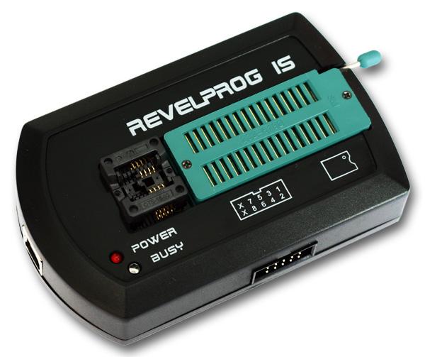
The Reveltronics flasher is certainly the most painless option. It is more expensive and may take a few days to arrive from Poland.

The Raspberry Pi kit you linked will also work. If using the Raspberry Pi, the procedure is as follows:

PARTS NEEDED:
  • Raspberry Pi kit with SD Card, heat sinks, power supply, and HDMI cable. The Canakit has all of these items.
  • Jumper wires such as this pack consisting of M/M, M/F, and F/F.
  • 8-pin SOI clip such as:

PROCEDURE:
  1. The kit you referenced comes with a Micro SD Card with SD Card adapter. On the Mac, download Raspbian Buster with desktop and recommended software from here.
  2. Then download and install Balena Etcher on the Mac.
  3. Insert Micro SD Card into the Mac (you'll need USB SD Card reader) and burn the Raspbian Buster image to the SD Card with Balena Etcher. When it's done, the SD Card will have Linux ext4 file format, which is unrecognized on Mac. So just pull the card out.
  4. Insert SD Card into Raspberry Pi and boot. Everything is already set up.
  5. Then click the top left "Raspberry" icon, and select Raspberry Pi Configuration as shown:
    raspberry_pi_configuration.png
  6. Then select the Interfaces tab and click enable next to SPI (Serial Peripheral Interface) as shown:
    menucfg.png
  7. Reboot.
  8. Now you're ready.

However, turn off the Raspberry Pi:
  • When connecting wires to the GPIO pins.
  • When connecting SOI Clip to the GC-Titan Ridge.
 
Last edited:
However, turn off the Raspberry Pi:
  • When connecting wires to the GPIO pins.
  • When connecting SOI Clip to the GC-Titan Ridge.

I prefer working with live circuits. lol I will go down to Best Buy and pick that up, I have a bunch of wires with ends on them m/F from this project I was working on recently.

You still left out the final string to program the new flash to the TR lol. :beachball:
 
I prefer working with live circuits. lol I will go down to Best Buy and pick that up, I have a bunch of wires with ends on them m/F from this project I was working on recently.

You still left out the final string to program the new flash to the TR lol. :beachball:
Yes, intentionally left that out. If you'd like to be a beta tester, I'll PM the command line to you instead of posting it in public. Don't want the general public (yet) to do this.
 
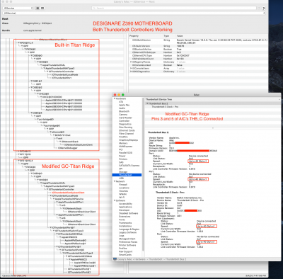
Can we install more than one Titan Ridge controller on Designare Z390?
These are preliminary findings. (This post still under construction.)​

Step 1:
  • Install GC-Titan Ridge in bottom long slot with modified SSDT for RP21, but original firmware.
  • This card has firmware version 43.
Result:
  • By connecting pins 3 and 5 in the Thunderbolt header of the GC-Titan Ridge, we force power to the controller and it appears under PR21.
  • USB-C devices connect and operate normally.
  • Thunderbolt devices do not function. Both cold connections and hot plug connections fail with Thunderbolt devices.
  • However, on-board Titan Ridge at RP05 works fine, including hot plug.
Screen Shot 2020-03-04 at 7.03.20 PM.png
Step 2:
  • Flash the modified firmware onto the card. The modified firmware is a downgrade to version 23.
    • Complete. Used flashrom on Raspberry Pi 4 to flash modified NVM 23 to GC-Titan Ridge.
    • It seems okay to downgrade the firmware from original NVM 43 to modified NVM 23.
  • Check Thunderbolt functionality, including Thunderbolt Bus, Local Node, and Hot Plug.
    • Complete. Thunderbolt Bus appears!
    • It is possible to use multiple Titan Ridge controllers on Designare Z390.
    • GC-Titan Ridge add-in-card must have Pins 3 and 5 tied together to force power.
    • Experiencing some issues, namely:
      • Thunderbolt devices need to be hot-plugged to be activated.
      • Second Thunderbolt port does not seem to work with Thunderbolt devices.
      • USB-C devices don't function on either port. UPDATE: This was my fault in not using unique names for XHC controllers on RP05 and RP21. I've changed them to XHC2 and XHC3, respectively.
      • These are preliminary issues and may be due to something I did or something I did not do.
Screen Shot 2020-03-04 at 7.47.57 PM.png

Strange Result #1:
  • The PowerColor Gaming Station eGPU has never worked on the Designare Z390 with hot-plug until now.
  • But the really strange result is this:
    • eGPU does not work properly when connected to modified GC-Titan Ridge.
    • eGPU does, however, work correctly when connected to internal Titan Ridge controller.
    • As long as Thunderbolt Bus is present (even if Thunderbolt Bus is from GC-Titan Ridge only), then eGPU works on internal RP05. Even the menu bar icon is present and functioning on Designare Z390.
  • Wondering if we need to switch to MacPro 7,1 system definition...
Screen Shot 2020-03-04 at 8.22.50 PM.png

Screen Shot 2020-03-04 at 8.27.55 PM.png
 
Last edited:
Yes, intentionally left that out. If you'd like to be a beta tester, I'll PM the command line to you instead of posting it in public. Don't want the general public (yet) to do this.

Fair enough yes send it over in the PM. thanks... I just got back from best buy with the stuff needed.
 
Back
Top