- Joined
- Sep 8, 2017
- Messages
- 24
- Motherboard
- Asus prime b350m-a
- CPU
- Ryzen 3600x
- Graphics
- Radeon RX5700
Hi Gents,
I decided to build a my PC in the some old fahsion case and then I found G5.
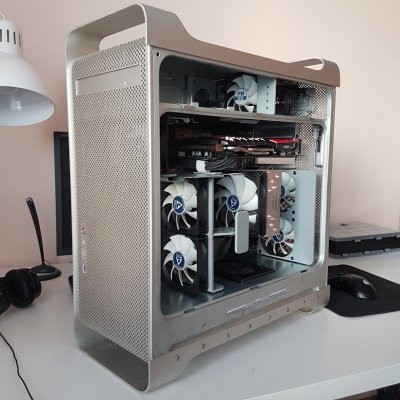
I like G5 case exterior so decided to do a cutting on interior, only.
As I do not using any Apple device, running PC on W10.
Mod Main Facts
Used Hardware
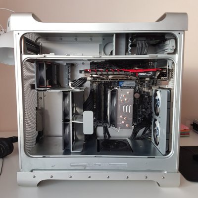
FINAL RESULT

REAR IO
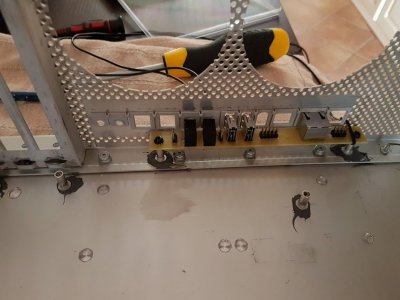
Biggest challenge was to keep untouched Rear IO as I decided to mount GPU to Rear Case PCIE bracket.
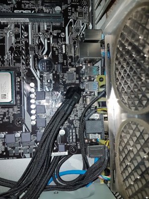
I like Zammykoo solution from InsanelyMAC with small extra PCB but can't use it as is cause Mobo is too close to Rear IO and his design is pretty wide. So did my own slim PCB design for Rear IO with smallest USB and Ethernet plug I found in local store. Audio and Ethernet is connected to Mobo external Rear IO, USB to internal Mobo header.
Rear IO PCB is fixed with G5 stand offs glued to back panel.
.

Front Panel
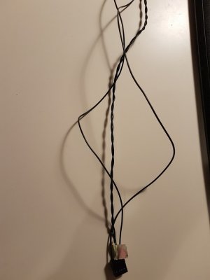
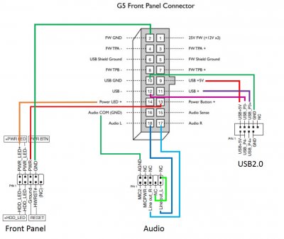
Used original connector where I pull out all unnecessary wires and extend by soldering wires and put "Dupont" connectors on the end for Mobo Headers. Important thing to make USB running data + and - wires have to be twisted each other to eliminate EMI. Attached my wiring diagram as well.

PSU
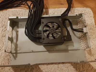
I like idea to put new PSU into original G5 PSU housing but as I don’t want to lose warranty I decided to use SFX PSU and put it in as is. I thought will fit perfectly and have to make just cut on top cover for fan size only but on the end PSU sticks out by 3-4 mm and have to make cut for PSU to avoid bottom cover bending. SFX PSU is fixed with double sided tape ;-)
Wires come with SFX PSU is really short so have to make my own wires used 1.0 mm2 CU wires and paracord for sleeving.
Fan Splitter & Acoustic Insulation
As like to have silent PC with good airflow decided to use Arctic PWM fans with original Fan Brackets.
Unfortunately my Mobo has only 1 case PWM fan header so have to make a fan splitter. Fans are powered from PSU.
My GPU has terrible coil whine so I attached acoustic insulation mat on the side cover (used in Mercedes Benz Doors ;-)


I decided to build a my PC in the some old fahsion case and then I found G5.
I like G5 case exterior so decided to do a cutting on interior, only.
As I do not using any Apple device, running PC on W10.
Mod Main Facts
- Untouched Exterior with 2x USB, Audio Output, MIC IN, Ethernet plug on Rear IO
- Fully Functional Front Panel expect Fireware, as I'm not using it
- Interior Layout close to original look with using G5 Fan Holders
- Using SFX PSU without loosing Warranty
- Perfect Airflow for overclocking and Silent Run
Used Hardware
CPU Cooler: Artic Freezer 33
GPU: MSI RX470 Gaming 4G
SSD: WD Blue PC SSD 250GB M.2
HDD: old 1TB SATA Seagate
RAM: Crucial 8GB DDR4 2666MHz CL16 Ballistix Sport LT
PSU: Corsair SF600
FANS: ARCTIC F9 PWM and F8 PWM
GPU: MSI RX470 Gaming 4G
SSD: WD Blue PC SSD 250GB M.2
HDD: old 1TB SATA Seagate
RAM: Crucial 8GB DDR4 2666MHz CL16 Ballistix Sport LT
PSU: Corsair SF600
FANS: ARCTIC F9 PWM and F8 PWM
FINAL RESULT


REAR IO
Biggest challenge was to keep untouched Rear IO as I decided to mount GPU to Rear Case PCIE bracket.
I like Zammykoo solution from InsanelyMAC with small extra PCB but can't use it as is cause Mobo is too close to Rear IO and his design is pretty wide. So did my own slim PCB design for Rear IO with smallest USB and Ethernet plug I found in local store. Audio and Ethernet is connected to Mobo external Rear IO, USB to internal Mobo header.
Rear IO PCB is fixed with G5 stand offs glued to back panel.
.


Front Panel
Used original connector where I pull out all unnecessary wires and extend by soldering wires and put "Dupont" connectors on the end for Mobo Headers. Important thing to make USB running data + and - wires have to be twisted each other to eliminate EMI. Attached my wiring diagram as well.


PSU
I like idea to put new PSU into original G5 PSU housing but as I don’t want to lose warranty I decided to use SFX PSU and put it in as is. I thought will fit perfectly and have to make just cut on top cover for fan size only but on the end PSU sticks out by 3-4 mm and have to make cut for PSU to avoid bottom cover bending. SFX PSU is fixed with double sided tape ;-)
Wires come with SFX PSU is really short so have to make my own wires used 1.0 mm2 CU wires and paracord for sleeving.

Fan Splitter & Acoustic Insulation
As like to have silent PC with good airflow decided to use Arctic PWM fans with original Fan Brackets.
Unfortunately my Mobo has only 1 case PWM fan header so have to make a fan splitter. Fans are powered from PSU.
My GPU has terrible coil whine so I attached acoustic insulation mat on the side cover (used in Mercedes Benz Doors ;-)


Last edited by a moderator:

