Contribute
Register

PSU not working after Modding it for Apple PSU Housing

Status
Not open for further replies.
Joined
Mar 1, 2013
Messages
943
Motherboard
GA-Z77X-UD5H
CPU
i7-3770K
Graphics
2x GEFORCE GT 640
Mac
  1. iMac
  2. MacBook Air
  3. MacBook Pro
  4. Mac Pro
Mobile Phone
  1. iOS
I am getting no power out to the fans, that are wired to a modular connection and on a 5v constant. I also am getting no readings on my PSU tester.

I started with a brand new, working (I tested it) SeaSonic PSU. I opened it, removed the guts and cut down the case to fit inside of the G5's PSU housing. I mounted the daughterboard next to the main PSU, but was careful not to put stress on the wiring. It is semi modular and as I was not going use the supplied PCI power cable, I shortened it, by cutting down the wires and capping them individually. The only soldering that I did was 1) extend the negative wire, by adding another piece and 2) soldering on a power connection to the terminals of the apple power input (I isolated this as a non-issue by removing that connection from the PSU and plugging in a standard cord).


What could be causing the PSU to not function? Any ideas on where I can go from here as far as testing, or do I need to just buy another one and start over hoping for better luck? I am doubting any PC repair shop near me, will actually test any of the internal connections and as I said it fails to display anything on my PSU tester. :banghead:
 
Ok so a couple other mods suggested I try the highly sophisticated 'paperclip' test. Reconnected original PSU fan and it did not start up upon testing :thumbdown:

Do you think I could get a TV repair or Electric shop to look/test the internals?
 
Ok so a couple other mods suggested I try the highly sophisticated 'paperclip' test. Reconnected original PSU fan and it did not start up upon testing :thumbdown:

Do you think I could get a TV repair or Electric shop to look/test the internals?

Or you could take a few photos of the AC input section and post them here.

Do you have a multimeter with a continuity test feature?

The next troubleshooting steps are to confirm that the AC input lines are terminated correctly.

Good modding,
neil
 
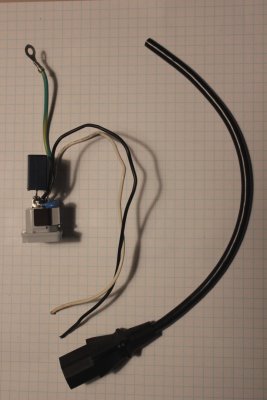
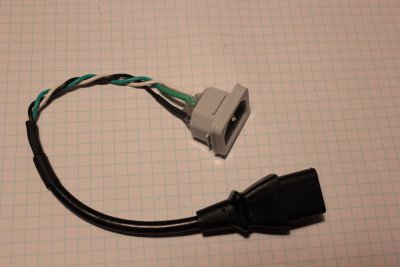
I didnt take any pics and currently its under heatshrink, so I 'borrowed' some from stiligFox. The following depicts the method I followed in making the AC connector. But I eliminated this as an issue by not using it and plugging a standard cord directly into the PSU. I do have a a multimeter with continuity.

g3geiSO.jpgr0eQcR6.jpg

What would be the next step?


Pic's courtesy of StiligFox. Hope he doesnt mind. Taken from: http://www.tonymacx86.com/powermac-g5/152927-stiligfoxs-powermac-g7.html thread
 
Okay this is a general process.

With the PSU NOT CONNECTED to the mains.

Disassemble the PSU so that you can probe the circuit traces. Do not have any devices connected to the PSU cable harness connectors.

Usually the AC power input wires are Brown and Blue. On the PSU, locate these input wires and the circuit traces that they soldered to.

Use your multimeter continuity test feature.

Read (or confirm continuity) from one AC input pin on the attached power cord to the trace on the PSU circuit board. Do the same for the other AC power input pin.

Read (or confirm continuity) from the ground terminal on the power cord to the case of the PSU.

The correct condition is continuity on each AC input power conductor to the PSU circuit card.

Let us know what you find.

Good modding,
neil
 
There is continuity from the attached cords' AC pins to each respective trace on the circuit board. Reading 0.0-0.1 ohms resistance.

There is also continuity from the ground terminal on the cord to the case of the PSU. Reading 0.0-0.1 ohms resistance as well.
 
There is continuity from the attached cords' AC pins to each respective trace on the circuit board. Reading 0.0-0.1 ohms resistance.

There is also continuity from the ground terminal on the cord to the case of the PSU. Reading 0.0-0.1 ohms resistance as well.

Okay that was the easy stuff. You now need to decide which way to proceed.

One option is to find a Tech that can trouble shoot the PSU for you. However the cost of trouble shooting maybe too high.

Another option is to start over with a new (tested) PSU. This maybe the lower cost way to proceed.

Good modding,
neil

I was afraid that was the next step... I ordered a new one to start over. Im just concerned that I don't know what I did wrong, to avoid this next time...

Any thoughts on what I could have done, or was it just bad luck?
 
You may also want to make sure that the bottom of the daughterboard is not touching the plate - I'm not sure if you did it the same way I did, but I used the same stand offs the PSU used originally to keep it safe from that...

Really sorry it's not working out :c
 
You may also want to make sure that the bottom of the daughterboard is not touching the plate - I'm not sure if you did it the same way I did, but I used the same stand offs the PSU used originally to keep it safe from that...

Really sorry it's not working out :c

Yeah, I followed your method exactly and used the same PSU standoffs....
 
Status
Not open for further replies.
Back
Top