
You are using an out of date browser. It may not display this or other websites correctly.
You should upgrade or use an alternative browser.
You should upgrade or use an alternative browser.
MacPro Fan PinOut
- Thread starter iDVD
- Start date
- Status
- Not open for further replies.
- Joined
- May 27, 2012
- Messages
- 759
- Motherboard
- DQ77KB
- CPU
- i7-3770S
- Graphics
- HD4000
- Mac
- Mobile Phone
A couple of Links might Help
My experience with an iMac G5 fan, which I think is similar.
http://www.tonymacx86.com/imac-mods/107859-kiwis-next-project-imac-g5-4.html#post681755
And another thread on a similar subject.
http://www.tonymacx86.com/powermac-g5/69889-info-g5-fans.html
The most important with a PC fan is that the speed control is done by changing the voltage between about 3v upto 12v. This voltage can be regulated by a PWM signal, but this control is actaully where all the Current is drawn from. The main 12V inpuit doesnt power the fan itself but is used for control circuitry only and uses minimal power.
This is opposite to a PC fan where the PWM speed control draws minimal power.
The solution is to use a transistor to convert the PC's PWM signal, into a high current for the fan control input. On the bottom left of the following schematic shows such a circuit.
http://www.tonymacx86.com/imac-mods/107859-kiwis-next-project-imac-g5-27.html#post985797
Kiwi
- Joined
- Jul 24, 2011
- Messages
- 25
- Motherboard
- CorebookX(2021)
- CPU
- i5-8259U
- Graphics
- Iris Plus 655
OK, let's make it clear.
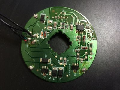
I cost one of my fans and analyzed the circuit.
Kiwi's second URL provides the right answer.
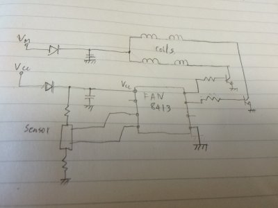
Vcc is power for just driver ic and Vm is for coils, as shown by my simplified circuit.
This means that Mac has high current PWM drivers on its main board cos they know exactly which fan will be mounted on their product.
Now think how to fit the fan into a normal PC. As you know, the optimal way is to provide 12V to Vcc and modulate the Vm.
But since there is a smoothing capacitor after a diode, you should not put a Pch mosfet in series. A inductor is needed.
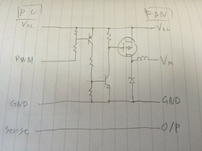
I suggest a simple circuit of one mosfet and two transistors, It can drive Vm powerful by the signal from PWM pin.
By the way, since the driver IC can work from as low as 4V and its consumption current is small, my first method still seems effective. All you have to prepare is just one resistor XD
I cost one of my fans and analyzed the circuit.
Kiwi's second URL provides the right answer.
Vcc is power for just driver ic and Vm is for coils, as shown by my simplified circuit.
This means that Mac has high current PWM drivers on its main board cos they know exactly which fan will be mounted on their product.
Now think how to fit the fan into a normal PC. As you know, the optimal way is to provide 12V to Vcc and modulate the Vm.
But since there is a smoothing capacitor after a diode, you should not put a Pch mosfet in series. A inductor is needed.
I suggest a simple circuit of one mosfet and two transistors, It can drive Vm powerful by the signal from PWM pin.
By the way, since the driver IC can work from as low as 4V and its consumption current is small, my first method still seems effective. All you have to prepare is just one resistor XD
Attachments
- Joined
- Jul 10, 2012
- Messages
- 25
- Motherboard
- Intel DQ77KB
- CPU
- Xeon E3-1230 V2
- Graphics
- GeForce GTX 770
- Mac
- Classic Mac
- Mobile Phone
OK, let's make it clear.
I cost one of my fans and analyzed the circuit...
(Diagram shows FAN8413 fan controller chip)
I found the datasheet here. The typical application circuit 1 is almost identical to your drawing.
https://www.digchip.com/datasheets/parts/datasheet/161/FAN8413M.php
No PWM speed control here.

***
I had I look at the fan control circuits on a uniprocessor Power Mac G5 that I had just pulled out. Next to a 16V, 47uF capacitor sits a FR5505 P-channel MOSFET. I also checked the 4-pin system fan connector on my GA-EG41MFT-US2H motherboard and saw a PA102FDG P-channel MOSFET next to a 100uF capacitor. Both MOSFETS are of similar size and thermal rating fully able to drive a fan with several amps of current. What Is the difference?
There is an underlying assumption that the Intel 4-pin fan standard drives the PWM line by a open-drain MOSFET. This would be simple, as it can be implemented inside an Integrated circuit without the need for a power transistor stage. The open-drain MOSFET would always be N-channel. A P-channel MOSFET would be more suited at providing power at 12 volts.
The argument for an open drain control line:
- Talk of a pull-up resistor on this thread.
- This Intel specification from 2004 speaks of PWM as a "control" signal: http://www.formfactors.org/developer\specs\rev1_2_public.pdf
- 4-pin fans work when connected to a 3-pin connector. This is only possible, if they have an inbuilt pull-up resistor. (See the question "Can I connect a 4-wire fan to a 3-wire connector?" here: http://pcbheaven.com/wikipages/How_PC_Fans_Work/ )
The Intel specification is vague in other ways too. It does not say what is "100% duty cycle", low voltage or high voltage. Assuming an open drain / open collector an a pull-up resistor, low voltage would mean full power. Is this so?
- Joined
- Jul 10, 2012
- Messages
- 25
- Motherboard
- Intel DQ77KB
- CPU
- Xeon E3-1230 V2
- Graphics
- GeForce GTX 770
- Mac
- Classic Mac
- Mobile Phone
The fans used in the Mac Pro and the Power Mac G5 are made by Delta Electronics, Inc. from Taiwan. Evidently the 92 mm fans used as the CPU fans and the rear fans in the G5 are model EFB0912HHE. It was for sale on Newegg from 2007 to 2014. Reviews say it is noisy. http://www.newegg.com/Product/Product.aspx?Item=N82E16835705013 (I do not know if 92 mm fans are used on the Mac Pro, but AFB1212HHE is the 120 mm equivalent: http://www.newegg.com/Product/Product.aspx?Item=N82E16835213005 )
"EFB-09-12-HHE" means EFB series, 90 mm, 12 volt, extra high power. I could no longer find the fan on the Delta web site, but similar products help in figuring out the specification.
Under "DC Brushless Fans & Blowers" I find the EFB Series:
- EFB0812HHB is 80x80x15mm. Voltage is 5.0 to 13.2 volts, rated current 0.33 Amps and power 3.96 Watts. Max speed is 3800 rpm. Other power eatings are LB, MB, HB (and HHB). rpm http://www.delta.com.tw/product/cp/dcfans/download/pdf/EFB/EFB80x80x15mm.pdf
The AFB Series has several 92 mm models:
- AFB0912HHF has a max speed is 3800 rpm at a 43 dB noise level and 0.28 Amps, 3.36 Wats
http://www.delta.com.tw/product/cp/dcfans/download/pdf/AFB/AFB92x92x32mm.pdf
- The 92 x 92 x 38 mm size models go up to AFB0912UHE (Ultra High Power?) with 30 Watt pover and 63 dB noise level.
http://www.delta.com.tw/product/cp/dcfans/download/pdf/AFB/AFB92x92x38mm.pdf
None of the datasheets say anything about the way the fans are controlled. All that is specified is two wires: "Lead Wires : UL 1007 AWG #24 OR Equivalent Red Wire Positive(+) Black Wire Negative(-)".
AliExpress lists several EFB0912HHE fans for sale. Appearances vary, but all seem to have a 3-pin connector. Most are black in color. http://www.aliexpress.com/cp/delta-efb0912hhe-online-shopping.html
Someone at Overclock posts photos of a gray EFB0912HHE. The circuit board shows a PWM connection where the original Mac fan had the V m (V motor) wire. http://www.overclock.net/t/1573325/need-help-with-92mm-delta-fan-pinout-efb0912hhe-apple-mac-version
***
This came up in a search: http://pinoutsguide.com/Motherboard/apple_fan_6pin_pinout.shtml
"Late model Apple laptops, iMacs and Mac Pros have analog speed control fans. This pinout and color scheme applies to fans made by Delta Electronics, models BFB0412HB (Apple P/N 603-5520), BFB0612H (Apple P/N 603-5519), BFB0812H (Apple P/N 603-6624), and others."
Even more interesting:
Pin Number: 1
Pin Name: Fan Speed Control
Description:
0-5 volts analog fan speed control.
0 volts=off, 5 volts = 100%, 2.5 volts = 50%, ...
Can also be controlled using a 5 volt PWM signal.
Google says that Apple part number: 603-5520 was used in a iMac G5 17inch A1058.
http://www.ifixmaccomputers.com/imac-g5-17-als-upper-fans-kit-apple-part-076-1183
Update May 28, 2016:
This discussion here suggest that even on the latest motherboards all headers labeled CPU_FAN are 4-pin PWM headers and all headers labeled SYS_FAN or CASE_FAN are voltage controlled 3-pin headers, no matter what the actual connector is like. No one seems to know where the case and system fans get their temperature readings from. It is suggested that all are in fact controlled by the CPU temperature.
Last edited:
- Joined
- Jul 10, 2012
- Messages
- 25
- Motherboard
- Intel DQ77KB
- CPU
- Xeon E3-1230 V2
- Graphics
- GeForce GTX 770
- Mac
- Classic Mac
- Mobile Phone
I connected the rear fans from a Power Mac G5 (single processor, 1.8 GHz) to a 5 volt supply and measured the current used by each pin. The results confirm what sanoayyk has said here earlier.
Pinout:
1. V(motor), top fan
2. Tacho
3. GND (common to both fans, two wires connected)
4. Vcc (common to both fans, two wires connected)
5. V(motor), bottom fan
6. Tacho
The test configuration is the same as in this drawing by Aman Fahimullah, except he has the pin numbering the wrong way. Pin no 1 is in the same place as it is on 3 and 4-pin fan connectors. (On the right in this picture.)

V(motor) draws 79 mA of current at 5 volts. Vcc only uses 6.3 mA.
I made a similar measurement on a 120 mm case fan: it used 22 mA @ 5 volts. The 92 mm fans on the G5 use 4 times as much energy on the same voltage as the PC fan. The PC was quiet at 5 volts but the G5 fan already made distracting noise.
Conclusions:
1) Mac fans are much more powerful than any PC fans. To keep the noise down they must be operated at far lower voltages.
The control logic in brushless motors serves the function of the commutator in traditional brushed DC motors. This needs about 5 volts on Vcc to operate. PC fans typically fail to start at voltages below 5 volts. By giving the control logic a separate Vcc wire, Apple allows the fans to be operated with V(motor) voltages as low as maybe 1.5 volts. (Vcc should always be connected directly to the 12 V or 5 V rail.)
2) There is no way to trivially connect a PWM output to a G5 or early Mac Pro fan. V(motor) is not a low power "control" signals, as some have suggested. Most of the power is drawn from the V(motor) pin. (Update, May 28, 2016: Here is a trivial circuit that converts PWM to analog voltage output.)
Also using motherboard 3-pin fan connectors may be difficult. The Mac fans may draw excessive amounts of current, especially if more than one fan is connected to the same control line. Even special 3-pin fan controllers may be ill suited, as PC fans expect voltages from 5 to 12 volts and Mac fans maybe 2 to 6 volts under normal operating conditions.
3) The simplest way to control Mac fans may be to "steal" the PWM signal from the CPU fan and use it to control all the case fans. The tachometer outputs may still be connected to different 3 or 4-pin headers on the motherboard to get RPM readings. In the simplest case there is also a normal PC-type CPU fan running to guarantee that the motherboard and BIOS get a normal tacho reading and do not start panicking about a loss of CPU cooler.
a) Connect Vcc to 12 volts, V(motor) to 5 volts and use a N-type MOSFET to switch the GND connection. The MOSFET can be directly controlled by the PWM signal.
The problem with this circuit is that the tachometer signal might not work. I guess it would be possible to direct the tacho line through a capacitor and still read it normally.
For higher speeds at 7 volts one might connect the whole fan circuit between the 5 volt and 12 volt rails. I guess it might still be possible to switch the N-type MOSFET on the 5 volt rail from the PWM output with only resistors and maybe a diode for protection. The mother board might have a Zener diode to prevent the pull-up pulling the line above 3.3 volts. See here: http://www.pavouk.org/hw/fan/en_fan4wire.html
b) The other option is to regulate current from the 12 volt or 5 volt rail. This requires extra circuitry an a circuit board. Sanoayyk already presented one possible circuit. Too many transistors for my taste. Cannot one just use a P-type MOSFET on the 12 volt rail and an opto-isolator or something to pass through the PWM signal?
Update May 28, 2016:
There seems to be a huge misunderstanding about what the voltage control or PWM needs to do to control the Apple fans. Some have suggested that the PWM output needs to be converted to a voltage output. Others have suggested that the Mac fans can be made to spin slower by somehow lowering the voltage. None of this is relevant.
Motherboard fan control does not aim at controlling the voltage or duty cycle based on temperature. In reality the tachometer feedback is part of the control loop. The circuitry aims at certain rpm based on temperature.
Quoting from a Maxim Integrated application note: Fan Control Advances: Consider Fan-Speed Regulation
I just read somewhere that the idle speed of Apple fans is 300 rpm. This is far lower than the minimum speeds for any PC fans. For Mac fans to operate normally under Hackintosh control someone must tell the fan controller to aim for a much lower fan speed.
Motherboards may have dedicated fan control chips, like the ones made by Maxim. These are programmed and controlled over the I2C / SMBus control bus. Another quote from the same application note:
How will the operating system know how to give the fan controller the right operating parameters?
Pinout:
1. V(motor), top fan
2. Tacho
3. GND (common to both fans, two wires connected)
4. Vcc (common to both fans, two wires connected)
5. V(motor), bottom fan
6. Tacho
The test configuration is the same as in this drawing by Aman Fahimullah, except he has the pin numbering the wrong way. Pin no 1 is in the same place as it is on 3 and 4-pin fan connectors. (On the right in this picture.)
V(motor) draws 79 mA of current at 5 volts. Vcc only uses 6.3 mA.
I made a similar measurement on a 120 mm case fan: it used 22 mA @ 5 volts. The 92 mm fans on the G5 use 4 times as much energy on the same voltage as the PC fan. The PC was quiet at 5 volts but the G5 fan already made distracting noise.
Conclusions:
1) Mac fans are much more powerful than any PC fans. To keep the noise down they must be operated at far lower voltages.
The control logic in brushless motors serves the function of the commutator in traditional brushed DC motors. This needs about 5 volts on Vcc to operate. PC fans typically fail to start at voltages below 5 volts. By giving the control logic a separate Vcc wire, Apple allows the fans to be operated with V(motor) voltages as low as maybe 1.5 volts. (Vcc should always be connected directly to the 12 V or 5 V rail.)
2) There is no way to trivially connect a PWM output to a G5 or early Mac Pro fan. V(motor) is not a low power "control" signals, as some have suggested. Most of the power is drawn from the V(motor) pin. (Update, May 28, 2016: Here is a trivial circuit that converts PWM to analog voltage output.)
Also using motherboard 3-pin fan connectors may be difficult. The Mac fans may draw excessive amounts of current, especially if more than one fan is connected to the same control line. Even special 3-pin fan controllers may be ill suited, as PC fans expect voltages from 5 to 12 volts and Mac fans maybe 2 to 6 volts under normal operating conditions.
3) The simplest way to control Mac fans may be to "steal" the PWM signal from the CPU fan and use it to control all the case fans. The tachometer outputs may still be connected to different 3 or 4-pin headers on the motherboard to get RPM readings. In the simplest case there is also a normal PC-type CPU fan running to guarantee that the motherboard and BIOS get a normal tacho reading and do not start panicking about a loss of CPU cooler.
a) Connect Vcc to 12 volts, V(motor) to 5 volts and use a N-type MOSFET to switch the GND connection. The MOSFET can be directly controlled by the PWM signal.
The problem with this circuit is that the tachometer signal might not work. I guess it would be possible to direct the tacho line through a capacitor and still read it normally.
For higher speeds at 7 volts one might connect the whole fan circuit between the 5 volt and 12 volt rails. I guess it might still be possible to switch the N-type MOSFET on the 5 volt rail from the PWM output with only resistors and maybe a diode for protection. The mother board might have a Zener diode to prevent the pull-up pulling the line above 3.3 volts. See here: http://www.pavouk.org/hw/fan/en_fan4wire.html
b) The other option is to regulate current from the 12 volt or 5 volt rail. This requires extra circuitry an a circuit board. Sanoayyk already presented one possible circuit. Too many transistors for my taste. Cannot one just use a P-type MOSFET on the 12 volt rail and an opto-isolator or something to pass through the PWM signal?
Update May 28, 2016:
There seems to be a huge misunderstanding about what the voltage control or PWM needs to do to control the Apple fans. Some have suggested that the PWM output needs to be converted to a voltage output. Others have suggested that the Mac fans can be made to spin slower by somehow lowering the voltage. None of this is relevant.
Motherboard fan control does not aim at controlling the voltage or duty cycle based on temperature. In reality the tachometer feedback is part of the control loop. The circuitry aims at certain rpm based on temperature.
Quoting from a Maxim Integrated application note: Fan Control Advances: Consider Fan-Speed Regulation
The MAX6650 is a true fan-speed regulator because it includes a tachometer output fan in its feedback loop.
I just read somewhere that the idle speed of Apple fans is 300 rpm. This is far lower than the minimum speeds for any PC fans. For Mac fans to operate normally under Hackintosh control someone must tell the fan controller to aim for a much lower fan speed.
Motherboards may have dedicated fan control chips, like the ones made by Maxim. These are programmed and controlled over the I2C / SMBus control bus. Another quote from the same application note:
The MAX6639 monitors the tachometer outputs of two fans and adjusts the duty cycles of its PWM outputs to force the fans to the correct speeds. As with the MAX6620, the MAX6639 includes several features such as detection of fan failures and adjustable PWM ramp rate to help reduce the audibility of fan-speed changes. In addition, the MAX6639 includes 2 channels of temperature sensing and a programmable temperature-to-RPM control algorithm that enables automatic control of fan RPM as a function of temperature.
How will the operating system know how to give the fan controller the right operating parameters?
Last edited:
- Joined
- Aug 16, 2011
- Messages
- 20
- Motherboard
- Apple
- CPU
- Intel
- Graphics
- AMD
What additional hardware do we need so that we can control the Apple pwm fans with the pc mainboard pwm output?
Wiring guide.
Wiring guide.
Last edited:
- Joined
- Aug 3, 2011
- Messages
- 32
- Motherboard
- Gigabyte Z370 Aorus ultra gaming 2.0
- CPU
- I7, 8700k
- Graphics
- AMD VEGA64
- Mac
- Mobile Phone
I successfully adapted a Mac Pro fan for my build.
orignal
Mac Pro fan pin out
1-> Ground
2->VCC fan logic
3->Taco reader or speed sense
4-> Voltage managed or control
PC Fan pin out
1-> Ground
2->Voltage managed or control
3-> taco reader speed sense
so I took out the pin4 out from the Mac Pro fan header and fed it into Pin2
the original PIN 2 marked as vcc from macpro fan has to be wired to any 12v vcc anywhere from smps or in my case CPU pump header. this power is only for fan logics. as already discussed
The modified pin-2 is the source of power draw.
result ----fan control with bios settings of fan in auto or voltage managed mode same as intel fans. max RPM 2750 normal at 40 degree is about 1800rpm and silent around 1400 rpm.
- Status
- Not open for further replies.
Copyright © 2010 - 2024 tonymacx86 LLC