- Joined
- Jul 28, 2010
- Messages
- 143
- Motherboard
- 10.11 and Windows 10
- CPU
- Core i5 4690k
- Graphics
- ASUS GTX 970 Mini 4GB
- Mac
- Classic Mac
- Mobile Phone
Updates
~This is post 1
~Post 2
~Post 3
~Post 4
~Post 5
~Post 6
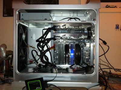
So after much research, and a lot of questions, I finally started my G5 mod. I was excited at first, but as I move along I get more and more scared I am going to break something. No worries though! I can assure you everything so far is going well. I try my best to photograph my progress, but sometimes I may get carried away and forget. So without further ado, let us begin!
IMG_0179.jpg
IMG_0180.jpg
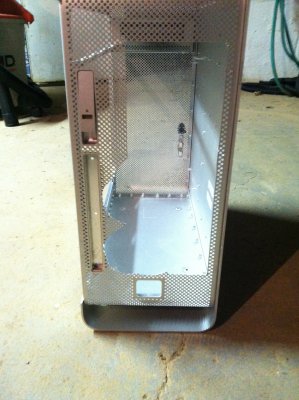
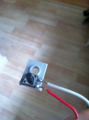
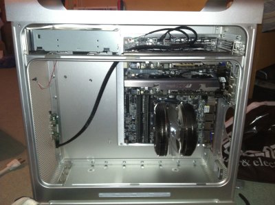
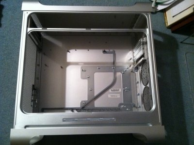
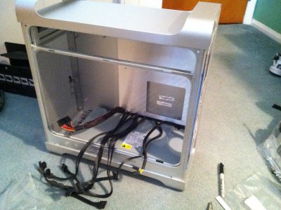
This took me quite a while to take apart. I was lucky to get a fully functioning late 2005 model (A1177), and had to go through a hole disassembly process.
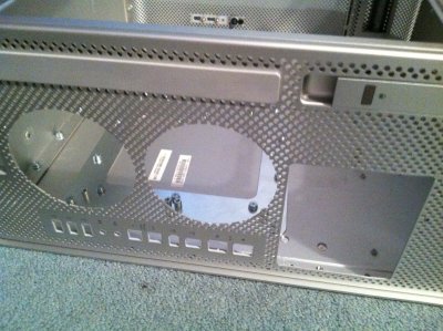
IMG_0181.jpg
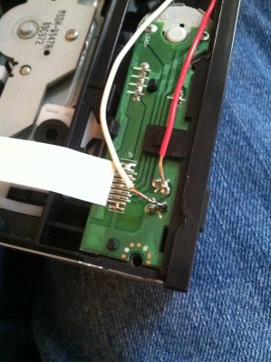
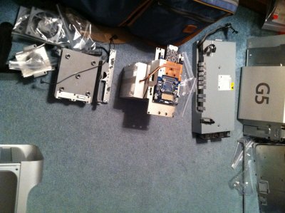
Here we can see all (or most) of the parts I had to remove from my computer. Some are in the boxes in the back to keep dust off of them, and to keep the safe (like the logic board). Also, pro tip for future G5'ers, bag all of your screws! This will really help you down the line, especially if you keep them near the original parts.
IMG_0182.JPG
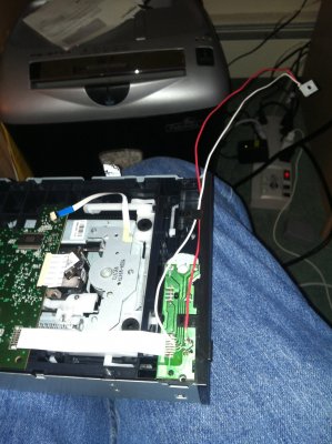
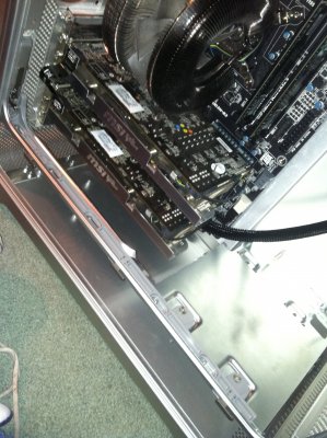
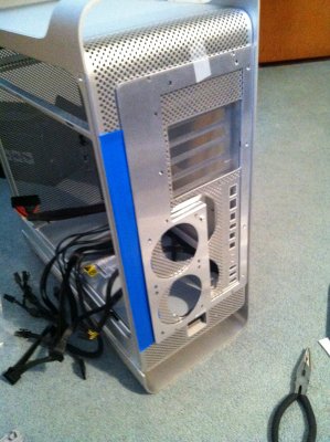
Started to remove the PCI slots. I cut myself being stupid doing this, so be careful!
IMG_0184.jpg
IMG_0185.jpg
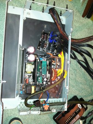
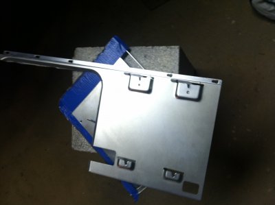
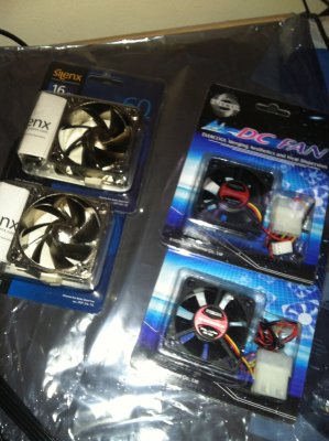
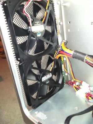
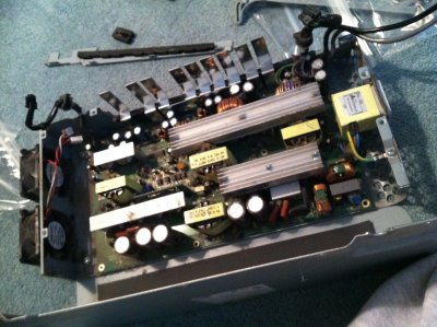
Cracked open my power supply. Had to clean out the dust and remove the power supply. I think I will get new fans for it. Not sure how I will plug them in yet, but I will find a way.
IMG_0188.jpg
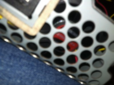
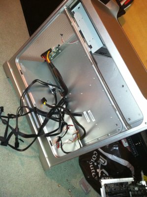
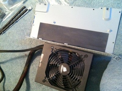
Finally got everything off, here you can see I am preparing to crack open my corsair semi modular power supply to put into the new case. This turned out to be a pain, and more than I wanted to deal with.
IMG_0190.jpg
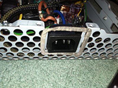
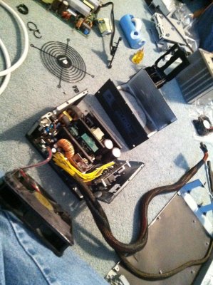
So I learned here that power supplies really hate being removed from their original incasement. I had to use a dremel to cut out the back and removed the socket. So far, that was the most scary part of building this. I have never cut metal, but there is a first time for everything.
To Be Continued....
Update 4/9/2012
IMG_0196.jpg
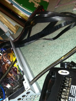
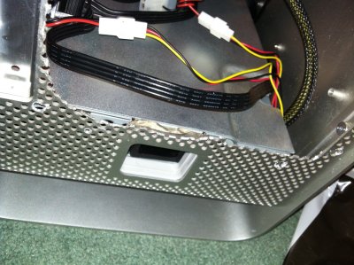
As you can see here, I am making sure my power supply fits in the case with the wires sticking out of it. The fans I plan on using are not here yet, I just ordered them, so I am hesitant to fully cap the power supply. Good thing is it fits!
IMG_0197.jpg
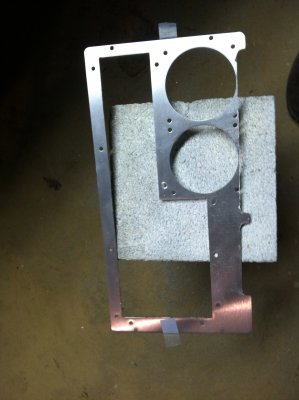
Now it is time to outline the place where I will be cutting the metal. I used masking tape and a sharpy marker. Unfortunately, the sharpy left some residue on the motherboard tray back, but it isn't visible.
~This is post 1
~Post 2
~Post 3
~Post 4
~Post 5
~Post 6
So after much research, and a lot of questions, I finally started my G5 mod. I was excited at first, but as I move along I get more and more scared I am going to break something.
No worries though! I can assure you everything so far is going well. I try my best to photograph my progress, but sometimes I may get carried away and forget. So without further ado, let us begin!IMG_0179.jpg
IMG_0180.jpg
This took me quite a while to take apart. I was lucky to get a fully functioning late 2005 model (A1177), and had to go through a hole disassembly process.
IMG_0181.jpg
Here we can see all (or most) of the parts I had to remove from my computer. Some are in the boxes in the back to keep dust off of them, and to keep the safe (like the logic board). Also, pro tip for future G5'ers, bag all of your screws! This will really help you down the line, especially if you keep them near the original parts.
IMG_0182.JPG
Started to remove the PCI slots. I cut myself being stupid doing this, so be careful!
IMG_0184.jpg
IMG_0185.jpg
Cracked open my power supply. Had to clean out the dust and remove the power supply. I think I will get new fans for it. Not sure how I will plug them in yet, but I will find a way.
IMG_0188.jpg
Finally got everything off, here you can see I am preparing to crack open my corsair semi modular power supply to put into the new case. This turned out to be a pain, and more than I wanted to deal with.
IMG_0190.jpg
So I learned here that power supplies really hate being removed from their original incasement. I had to use a dremel to cut out the back and removed the socket. So far, that was the most scary part of building this. I have never cut metal, but there is a first time for everything.
To Be Continued....
Update 4/9/2012
IMG_0196.jpg
As you can see here, I am making sure my power supply fits in the case with the wires sticking out of it. The fans I plan on using are not here yet, I just ordered them, so I am hesitant to fully cap the power supply. Good thing is it fits!
IMG_0197.jpg
Now it is time to outline the place where I will be cutting the metal. I used masking tape and a sharpy marker. Unfortunately, the sharpy left some residue on the motherboard tray back, but it isn't visible.
Attachments
-
 IMG_0179.jpg1.6 MB · Views: 1,377
 -
 IMG_0180.jpg2.3 MB · Views: 1,312
 -
 IMG_0181.jpg2.1 MB · Views: 1,316
 -
 IMG_0182.JPG1.8 MB · Views: 1,307
 -
 IMG_0184.jpg2.4 MB · Views: 1,330
 -
 IMG_0185.jpg1.5 MB · Views: 1,316
 -
 IMG_0188.jpg1.6 MB · Views: 1,312
 -
 IMG_0190.jpg2.3 MB · Views: 1,310
 -
 IMG_0196.jpg2.2 MB · Views: 1,254
 -
 IMG_0197.jpg2.3 MB · Views: 1,242