- Joined
- Jul 26, 2012
- Messages
- 73
- Motherboard
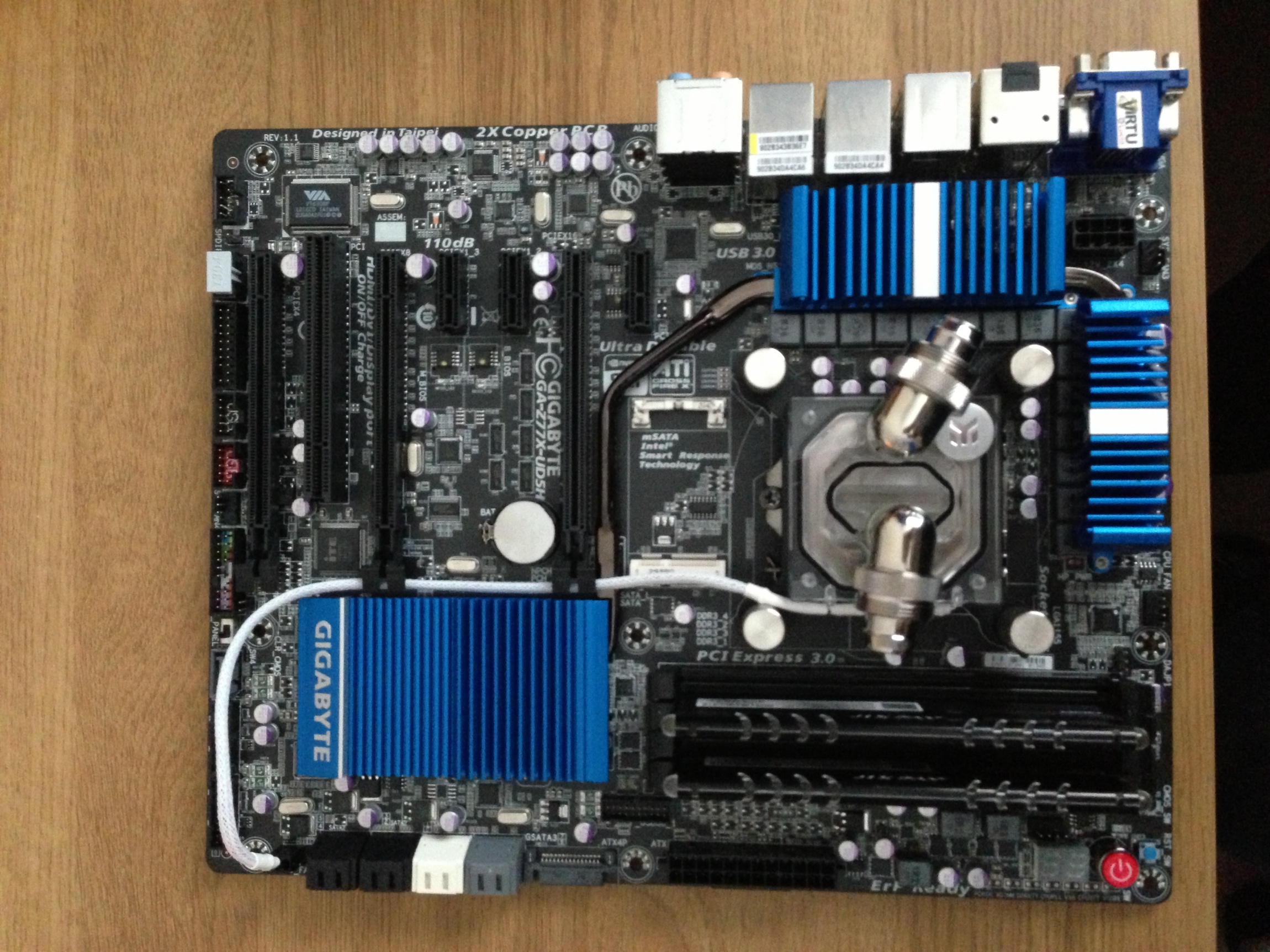
- Gigabyte Z77X-UD5H
- CPU
- Intel Core i5 3570k
- Graphics
- EVGA GTX 780 Ti 3GB
- Mac
- Classic Mac
- Mobile Phone
Project PowerMac i5
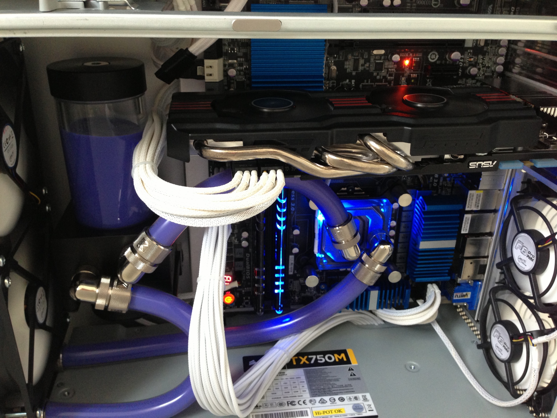
After many years of wanting to create 'my perfect computer' i finally took up the challenge of creating it. My aim was to create a Hackintosh that could run both OS's (primarily OS X), that had the feel of a Mac whilst having the essence of a gaming rig. It had to be visually pleasing both inside and out with water cooling and braided cabling. I seen many other mods on TonyMac Forums that gave me inspiration, One being minihack's and the other being brammee's.
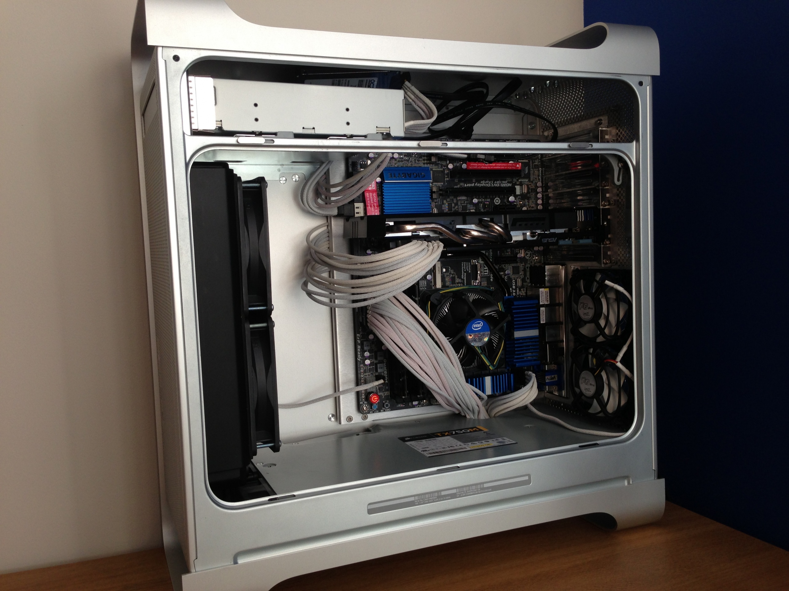
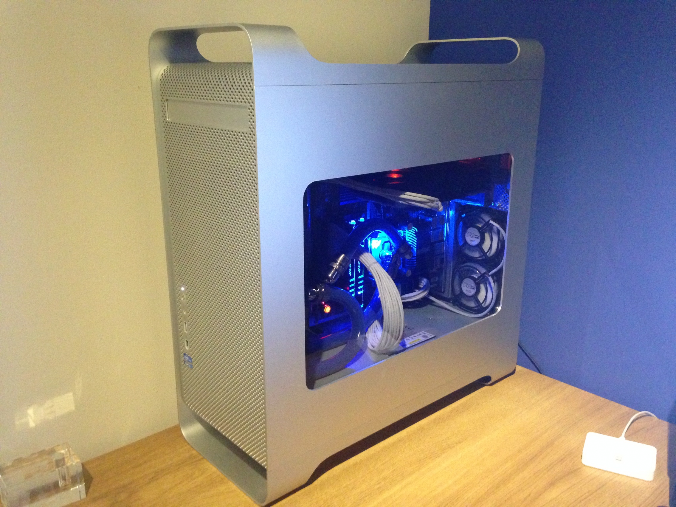
This was the final result
Specifications
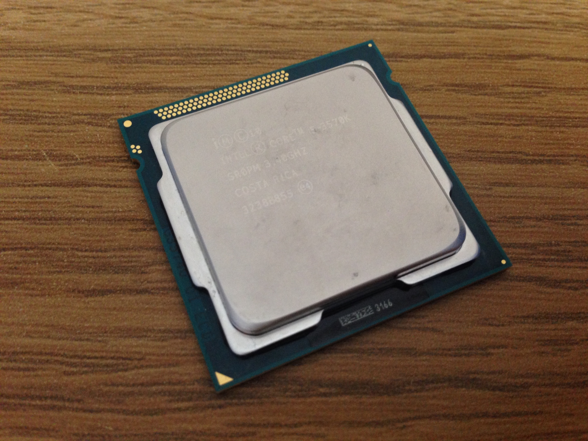
Intel Core i5 3570K 3.40GHz
Gigabyte Z77-UD5H
ASUS GTX 760 2GB OC
Avexir Core Blue 2666 8GB
2 OCZ Vertex 4 256GB
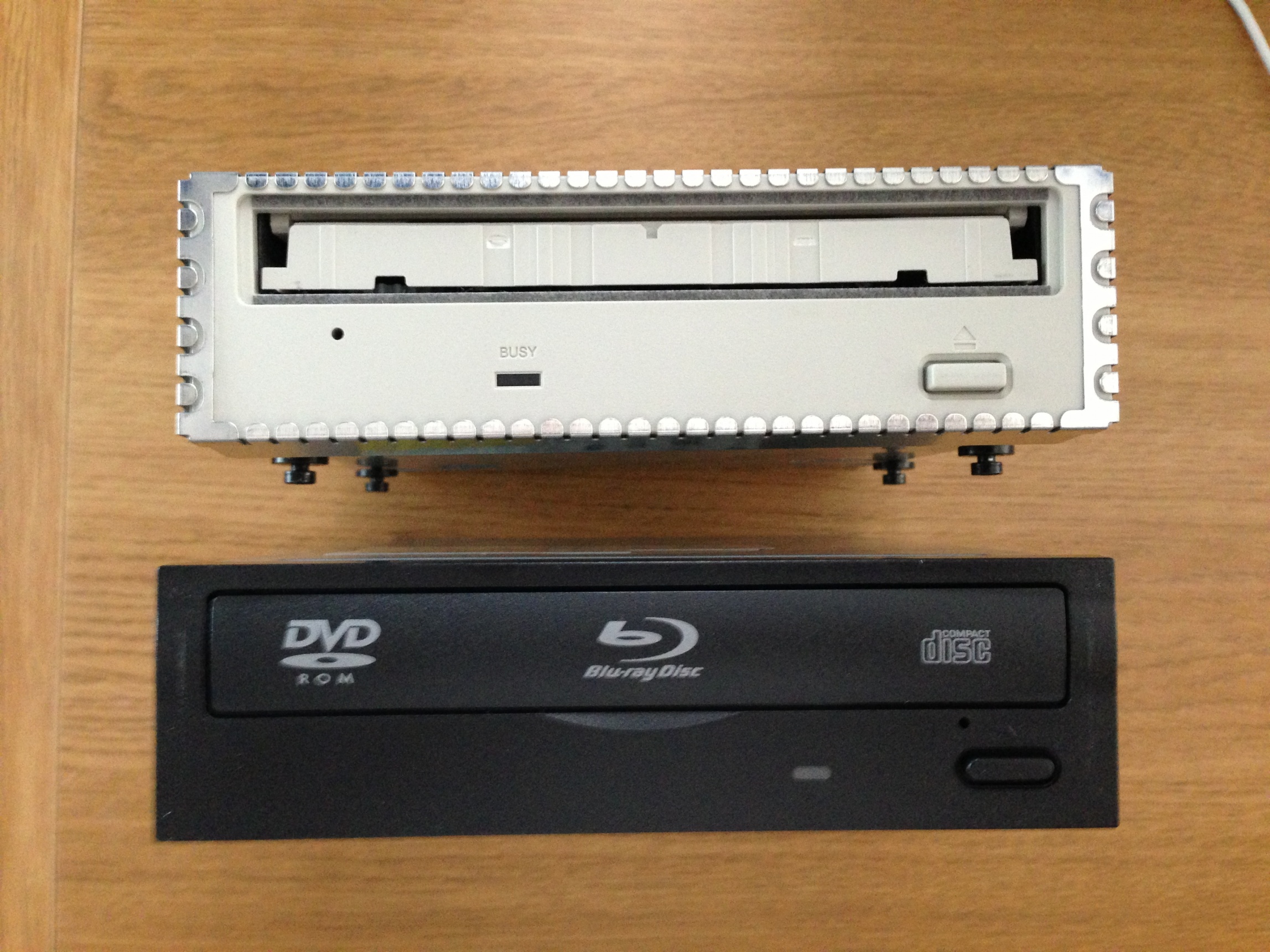
LG Blu-Ray Player
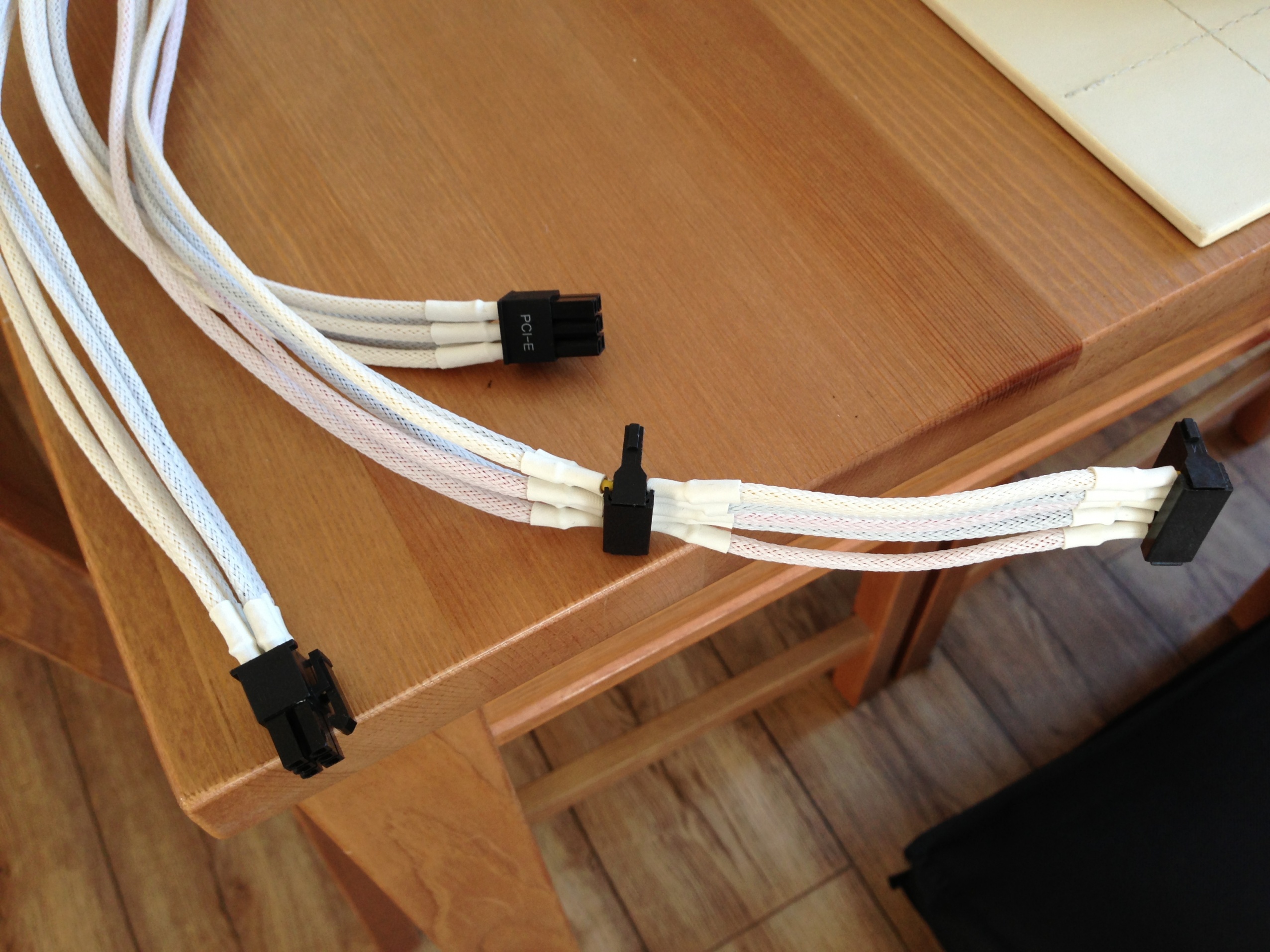
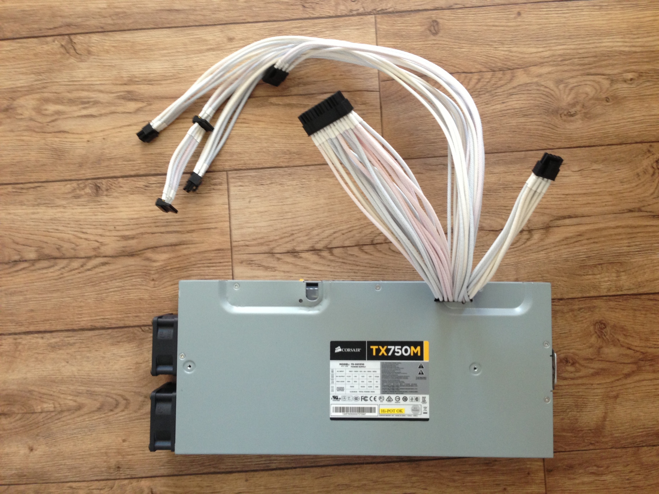
Corsair TX750M PSU
The Build
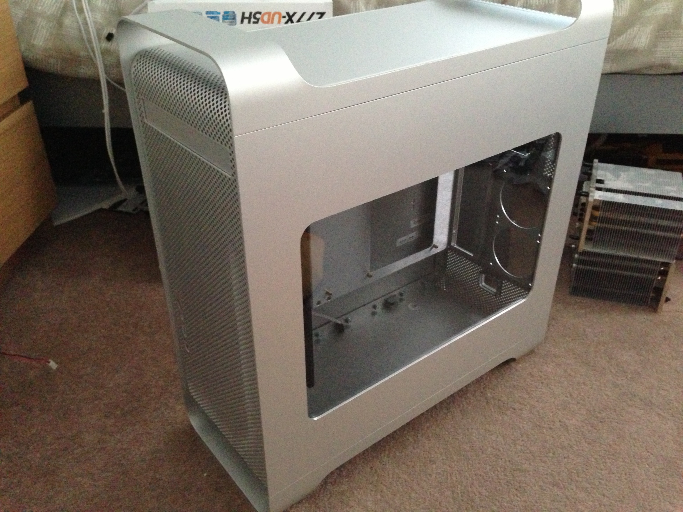
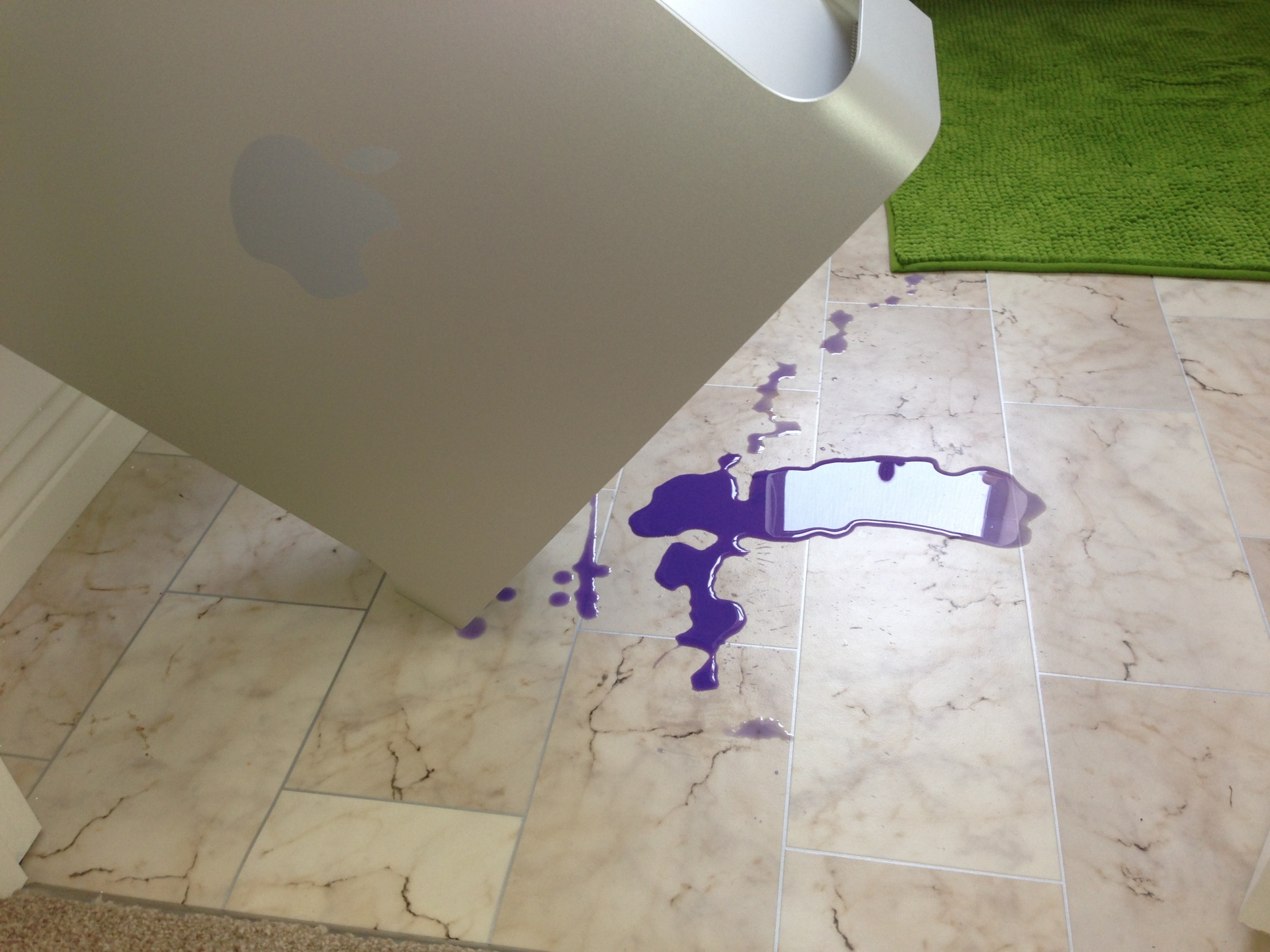
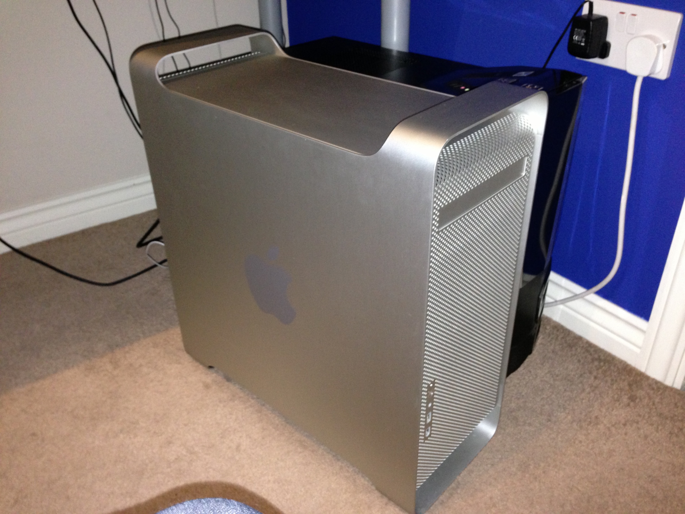
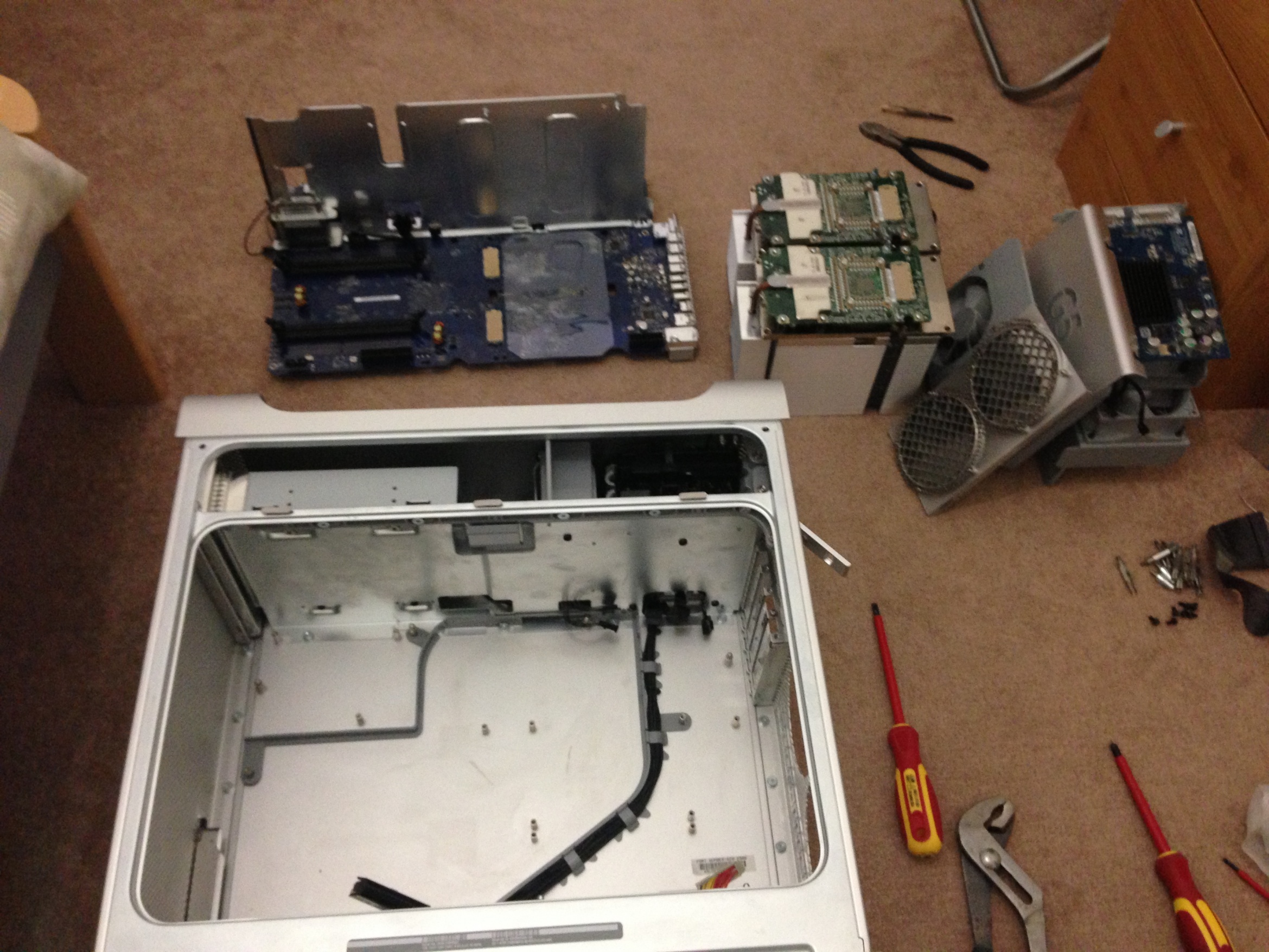
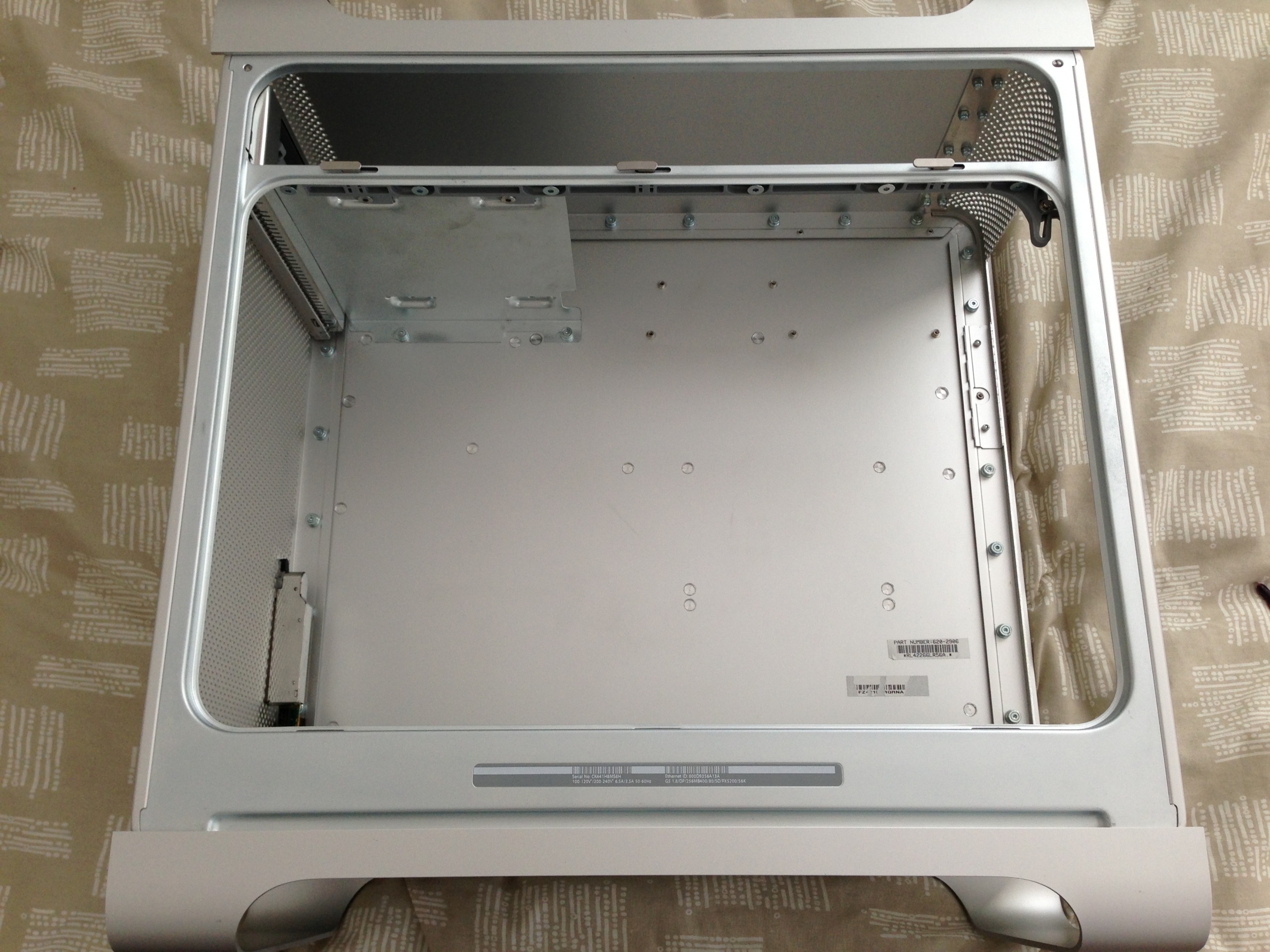
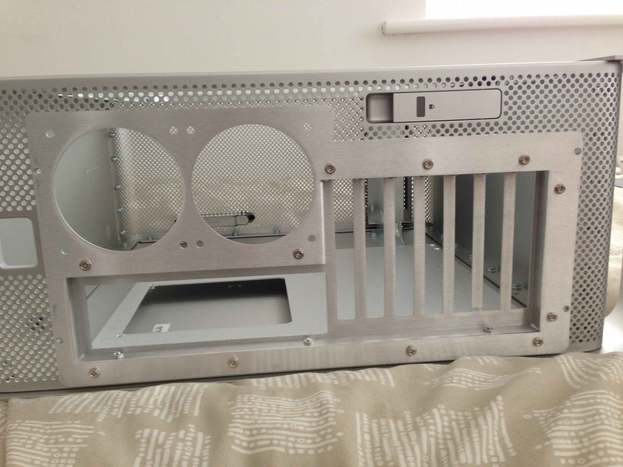
So, here is the Power Mac G5 Dual 1.86GHz 2004 Model, that i picked up in fully working order and in pretty much perfect condition (the reason i bought it). It came in its battered box and i picked it up from York, UK for £90.
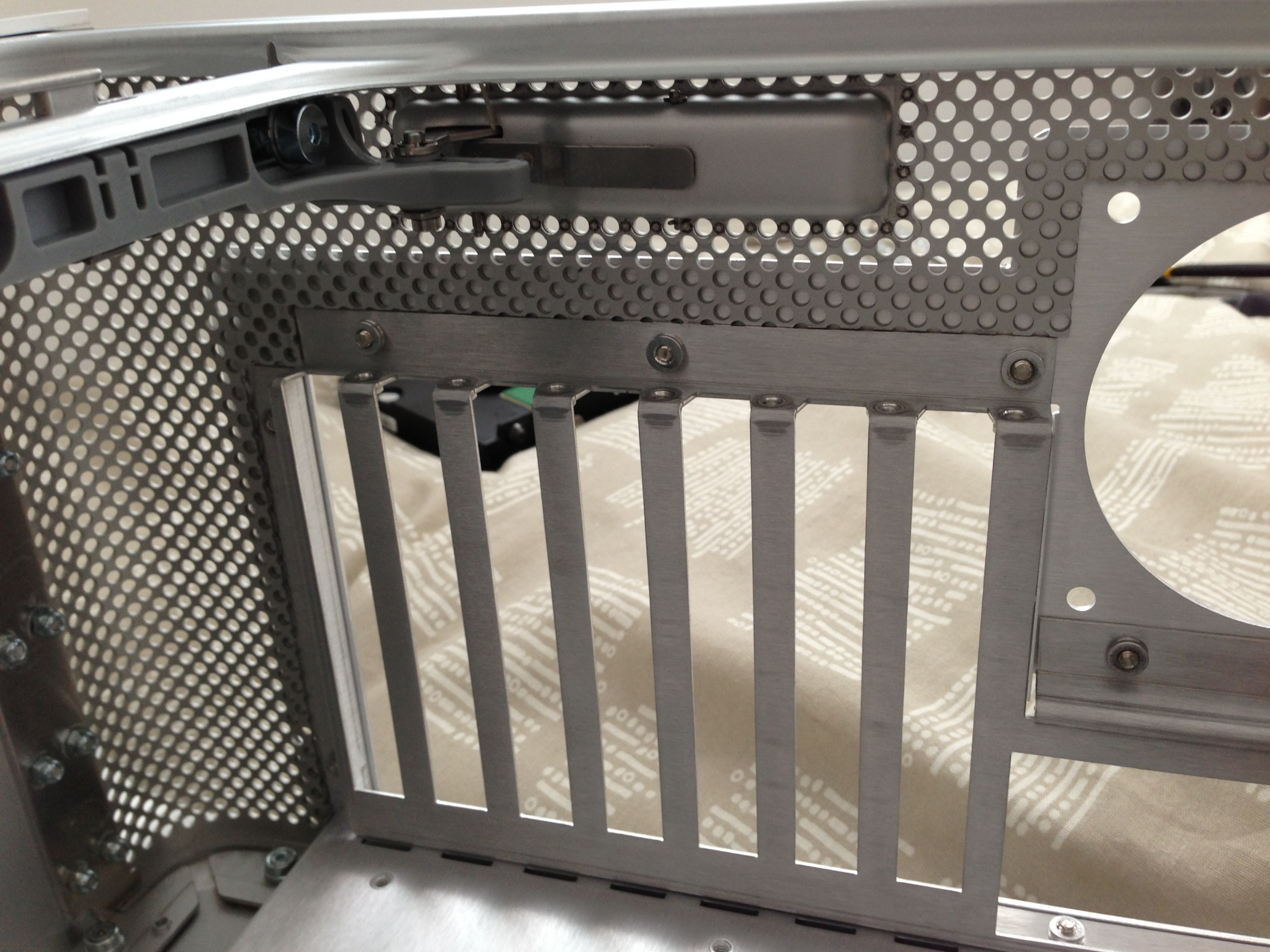
I had a little bit of a mess on with it before dismantling it ready for modification, but then got right to work stripping it out.
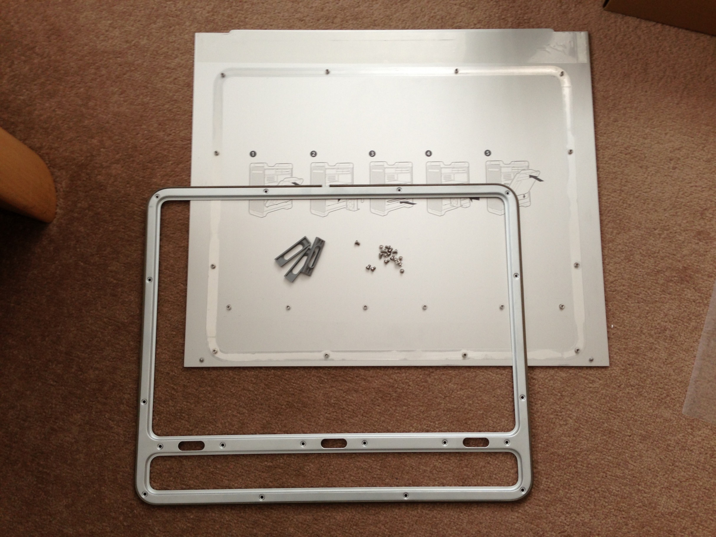
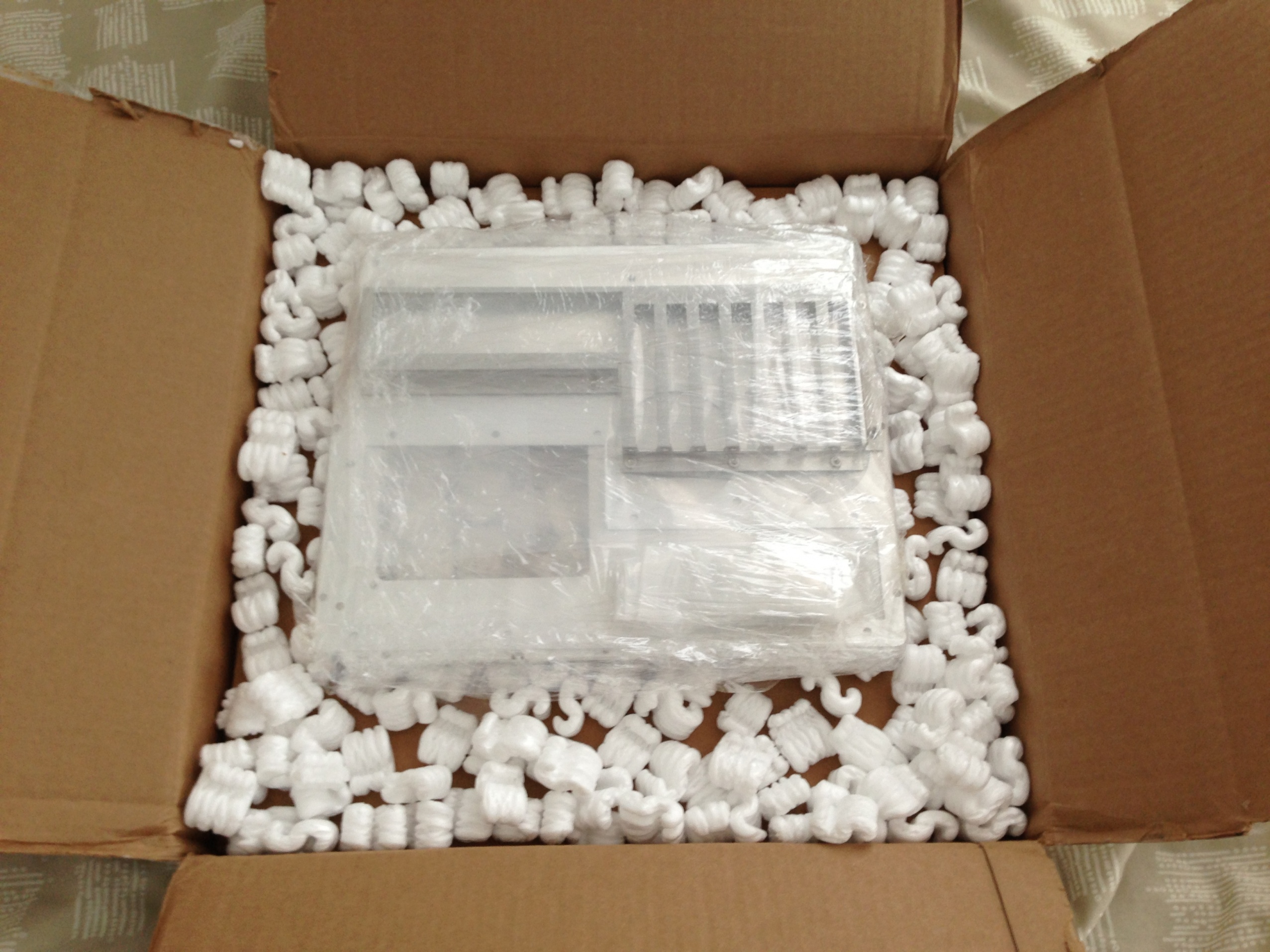
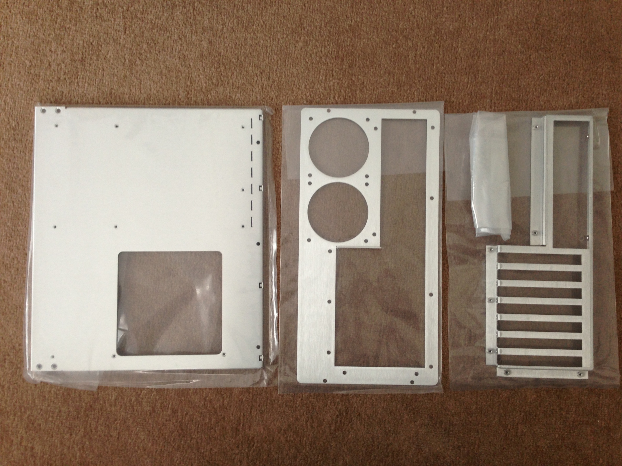
Now it sat there for a few months as i was waiting to finish my university term, but whilst i was waiting i ordered the Mountain Mods motherboard tray as i had heard it was very well made.
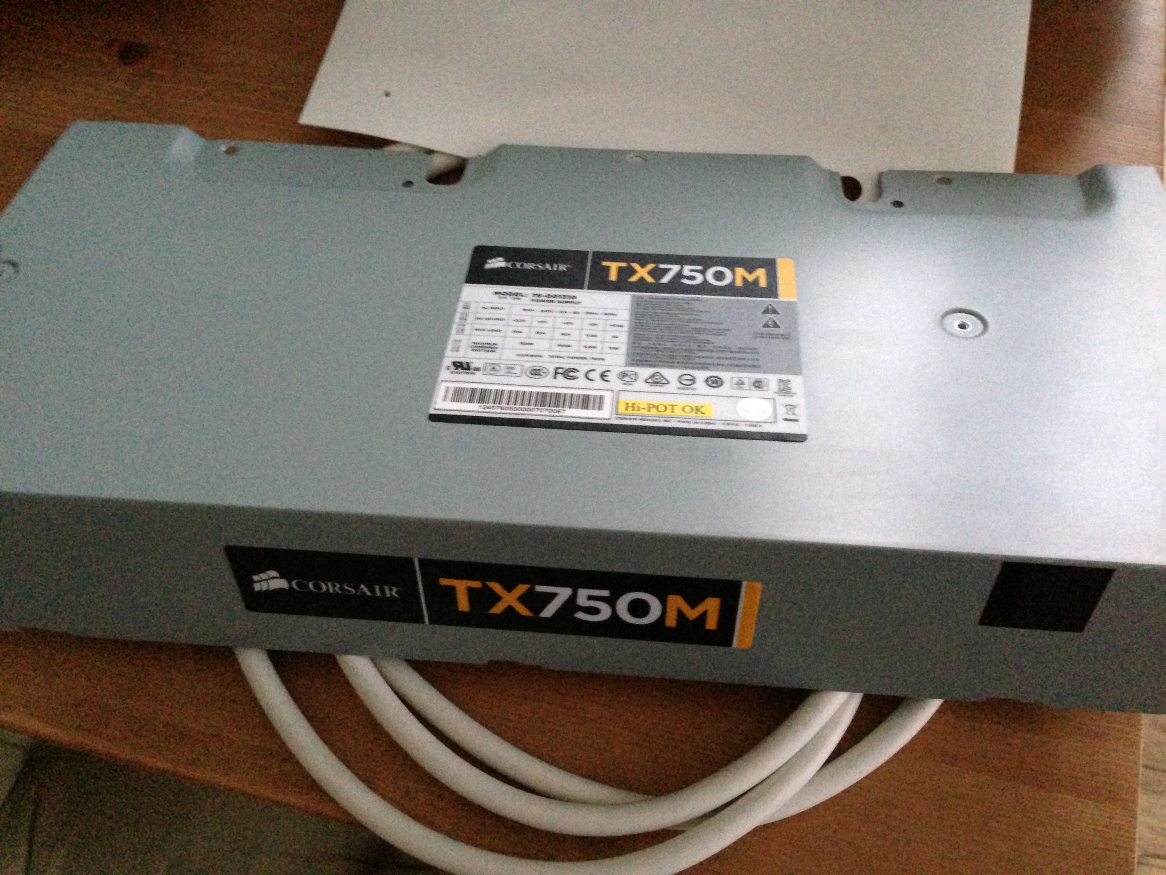
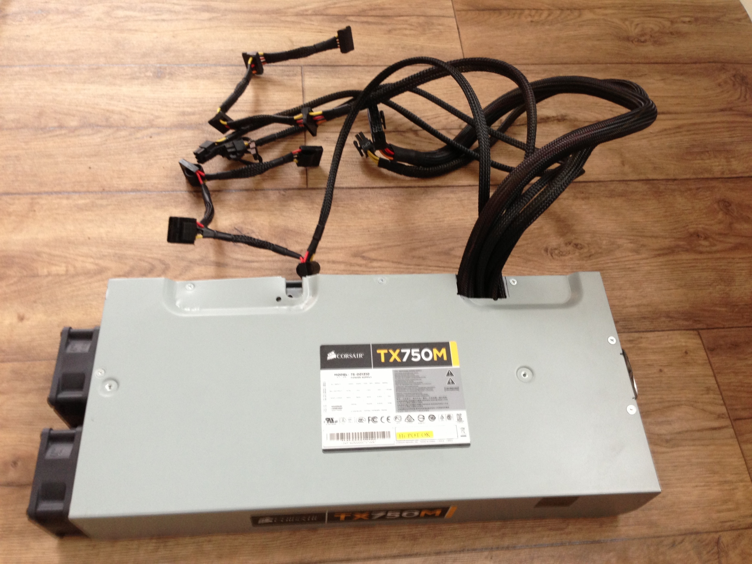
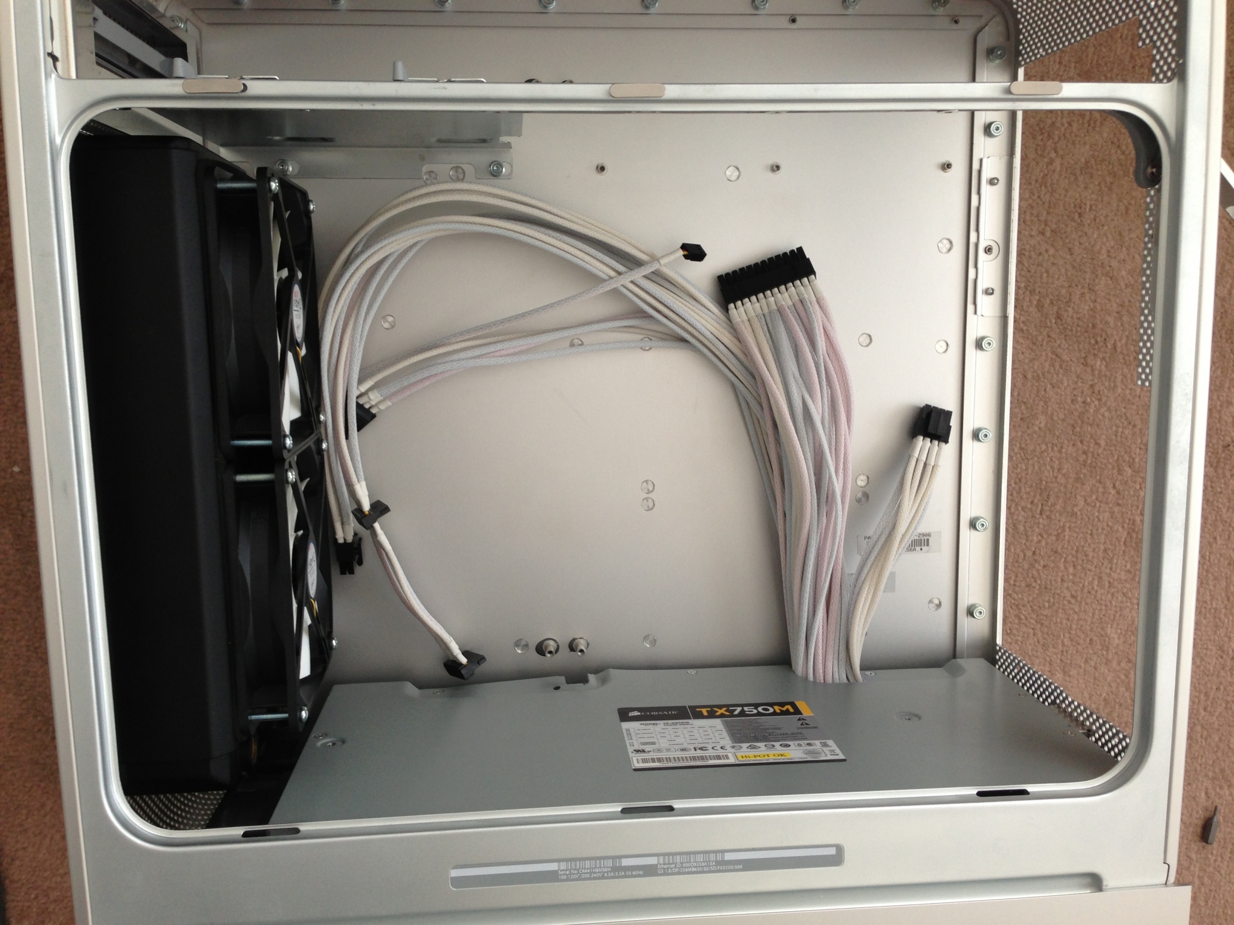
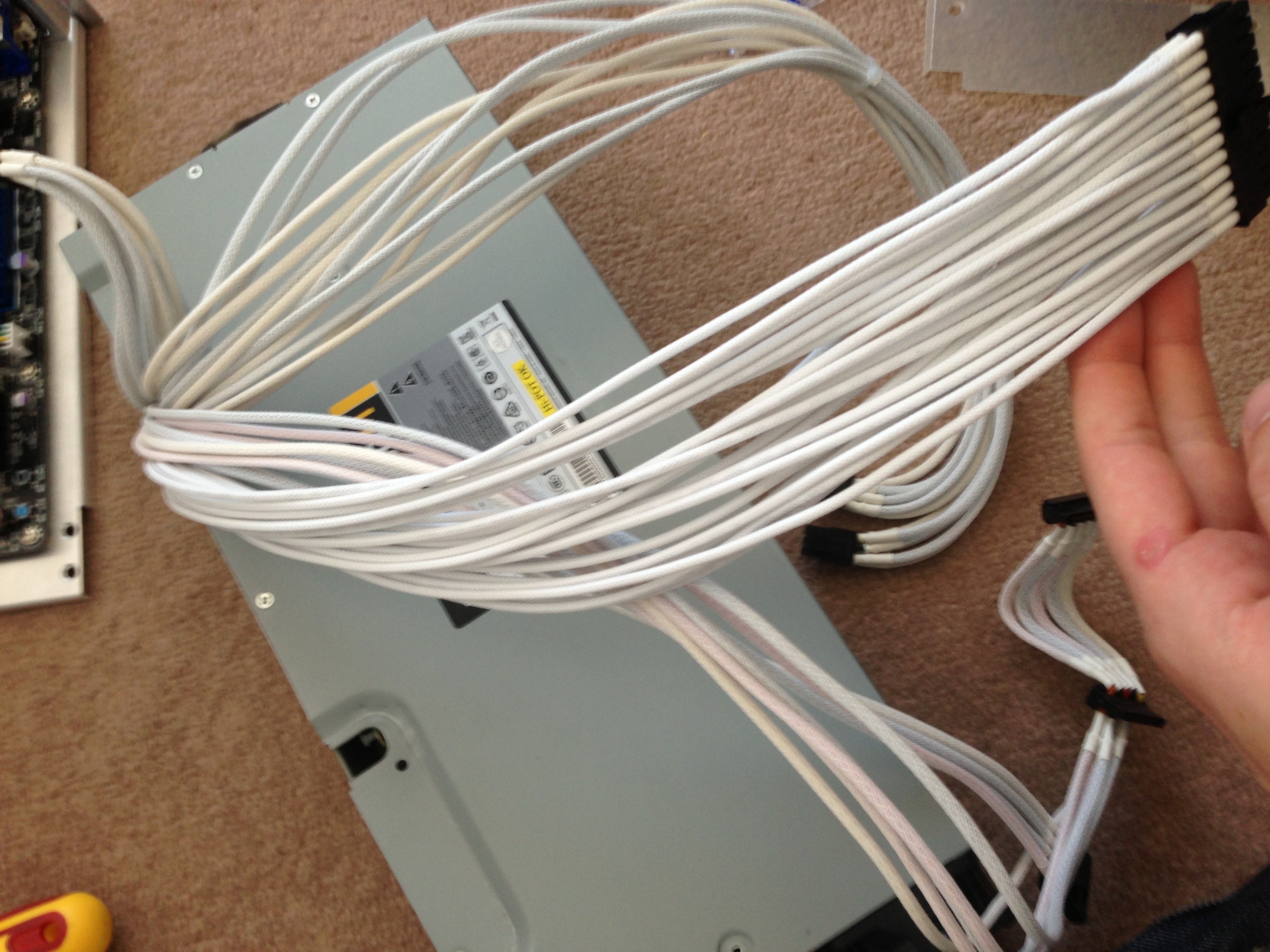
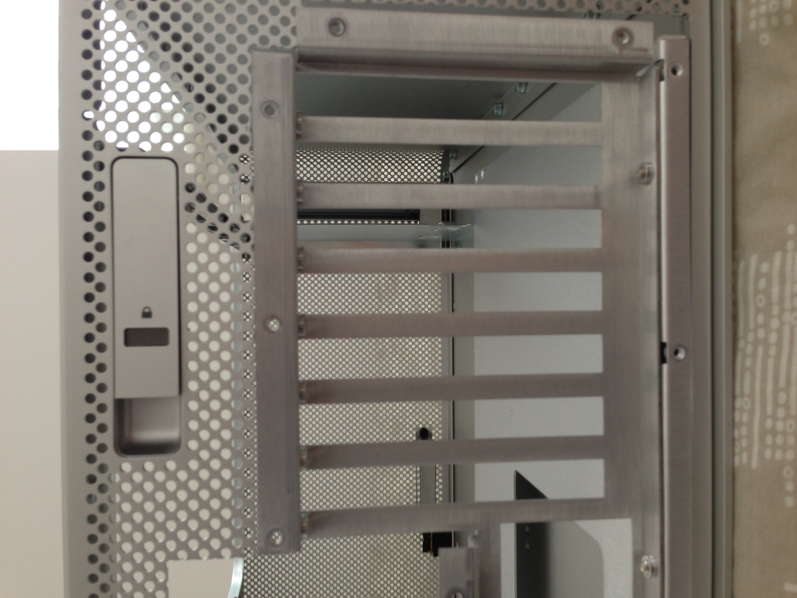
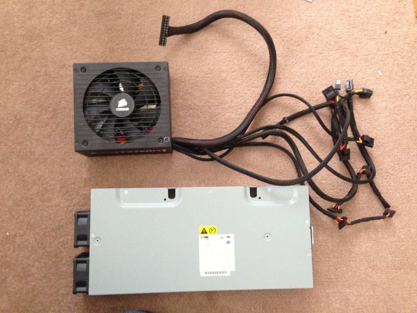
So my plan was to utilize the original PSU and modify the cables, but having been there before (An iMac G3 Project), modding PSUs is not the easiest thing to do. I decided that it would be best to take the easier route and build a new PSU into it. So i removed and prepped it ready for a Corsair CX750M.
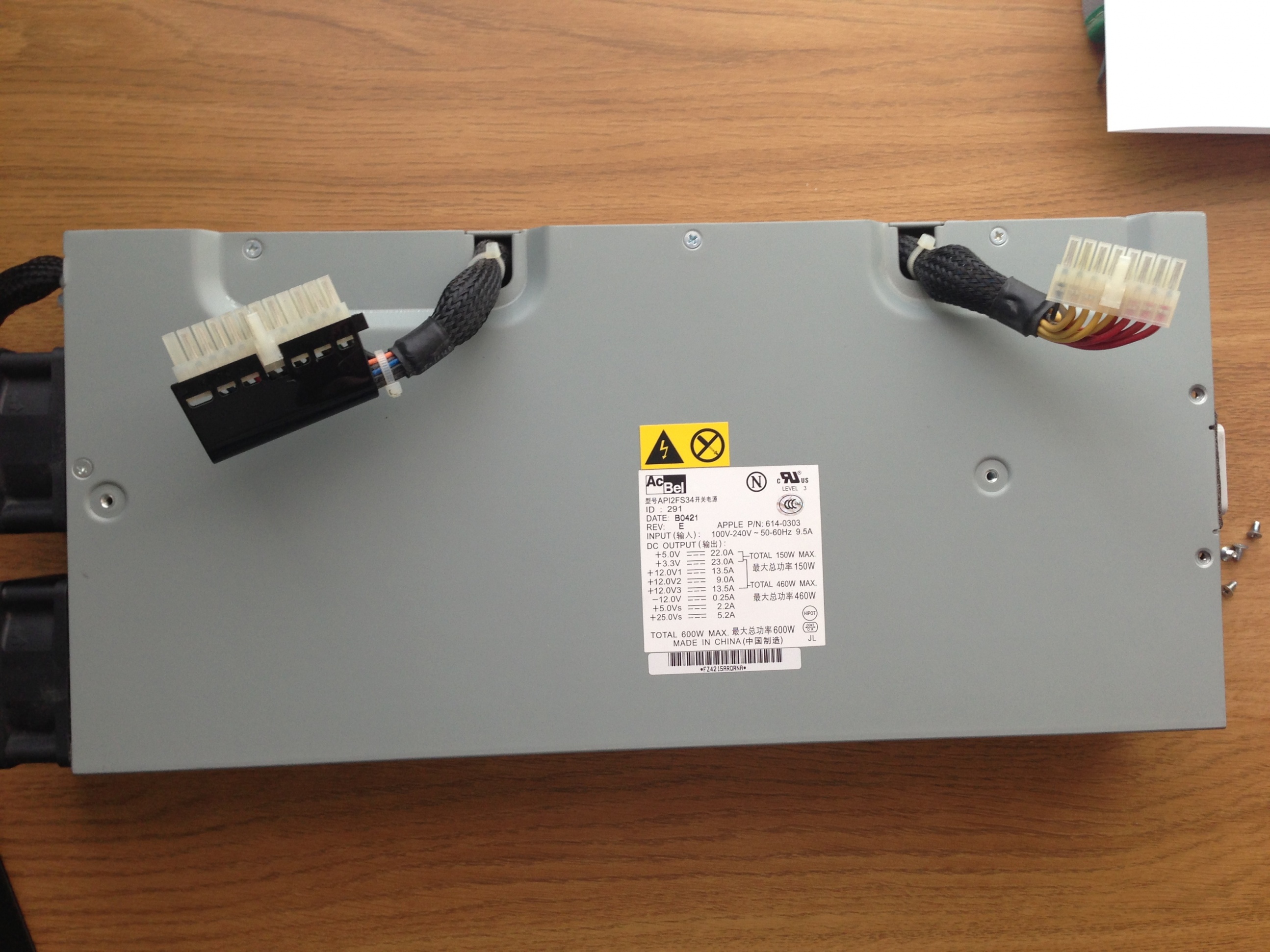
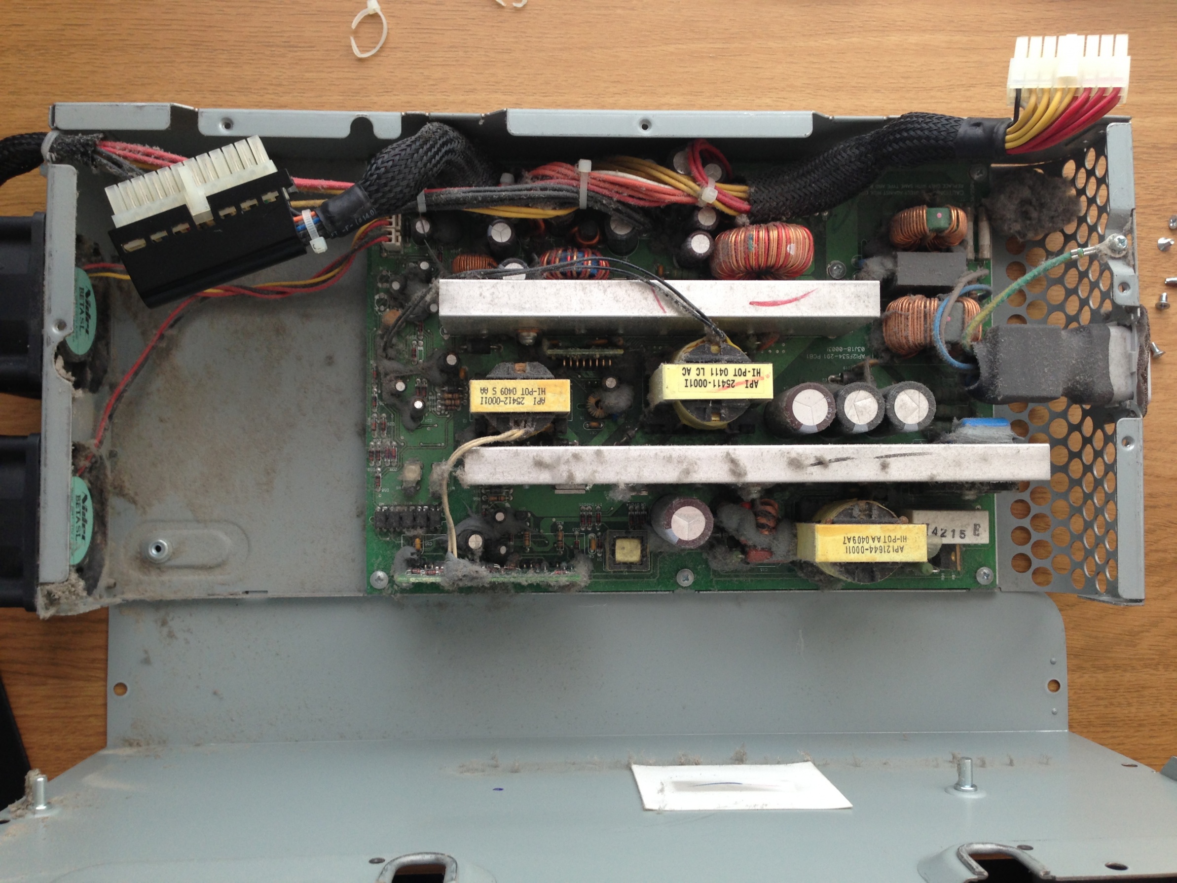

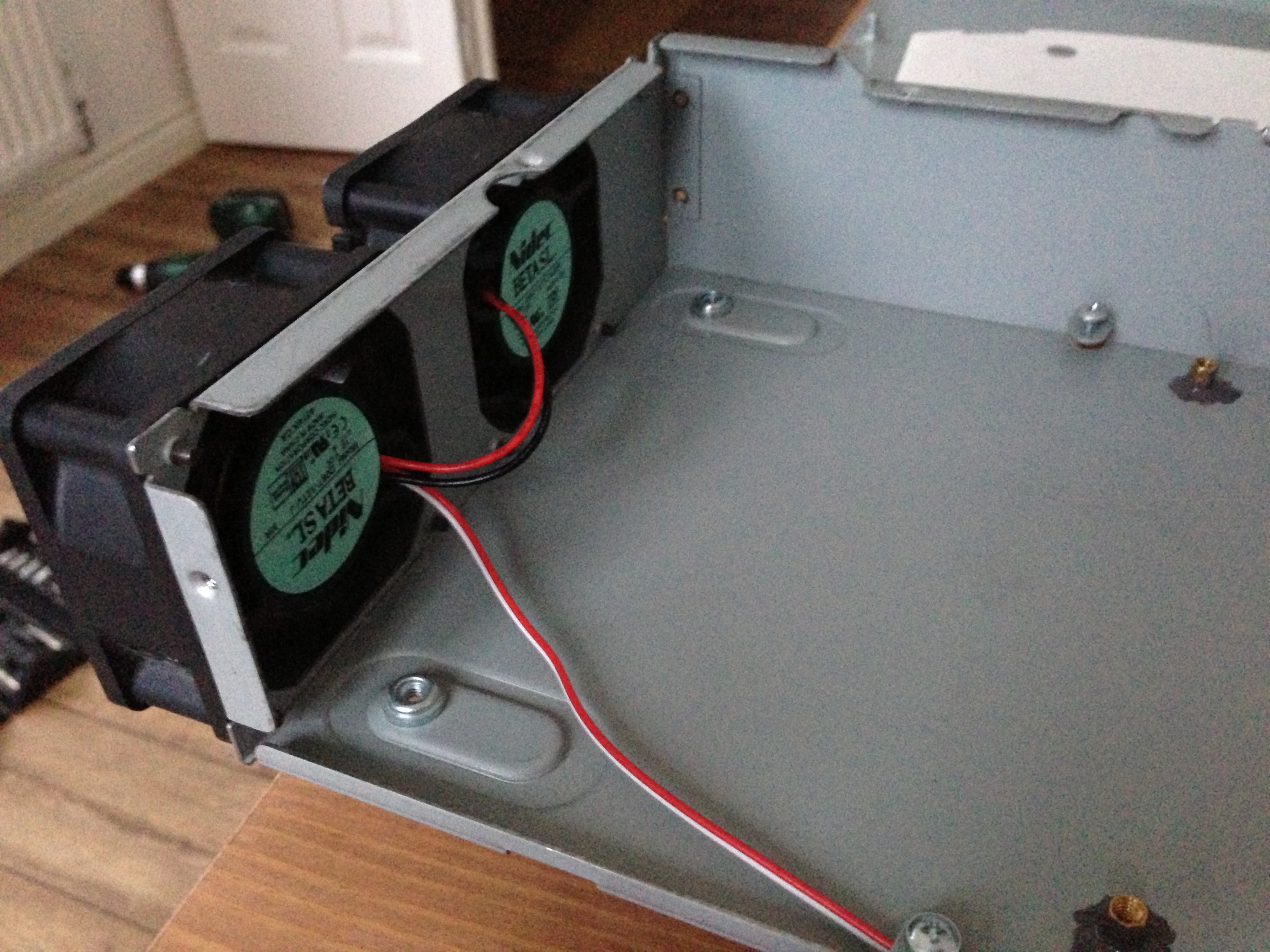
It was rotten inside that PSU! but anyways... I had planned to replace the PSU cover with a new bit of Aluminum as it will get rid of all the notches that were used for holding bits in its original state, but, unfortunately, as you will see later on it wasn't possible due to space constraints.

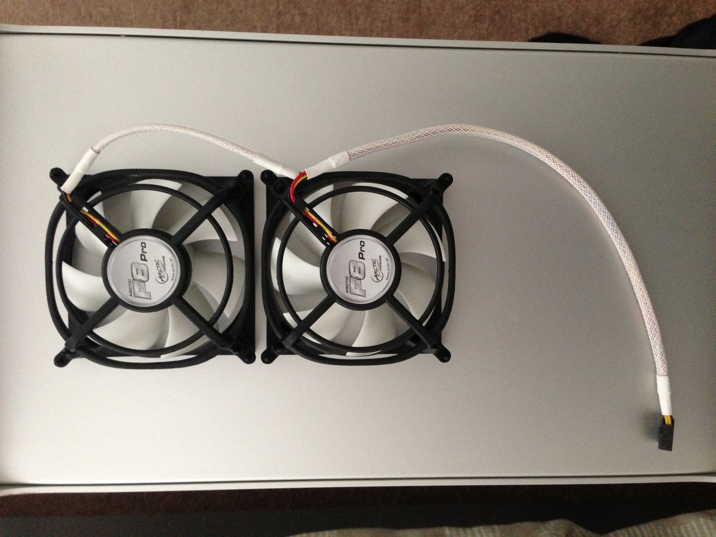
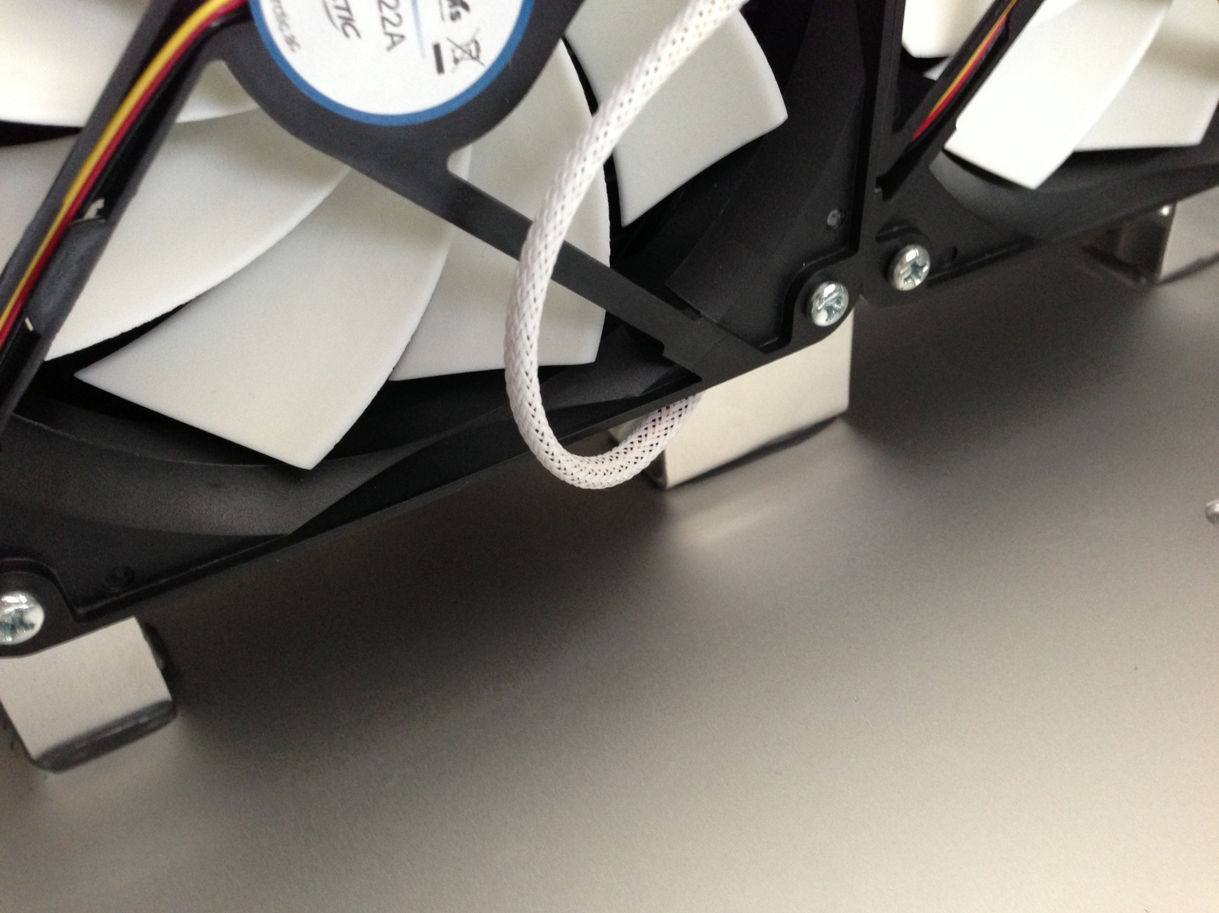
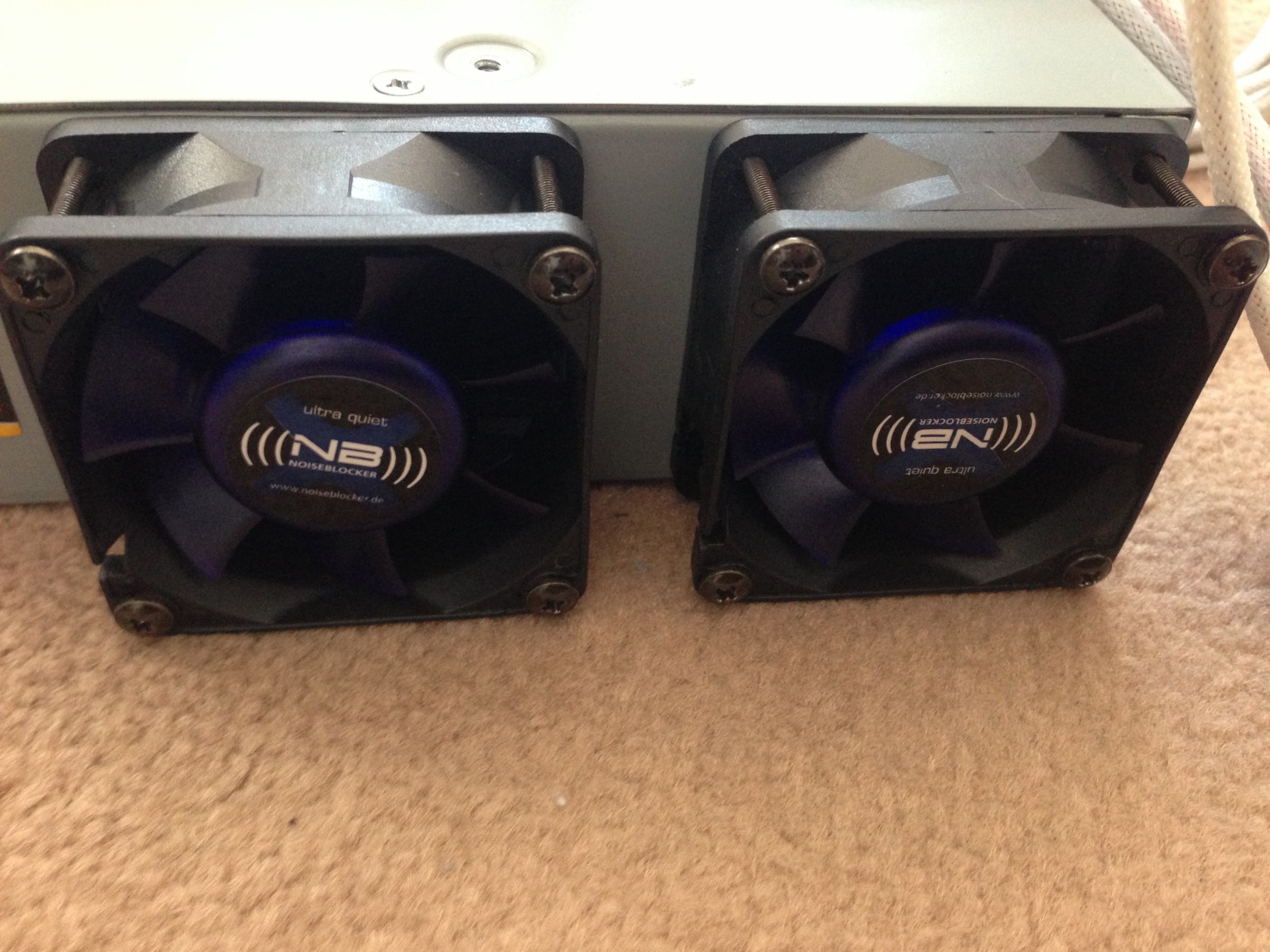
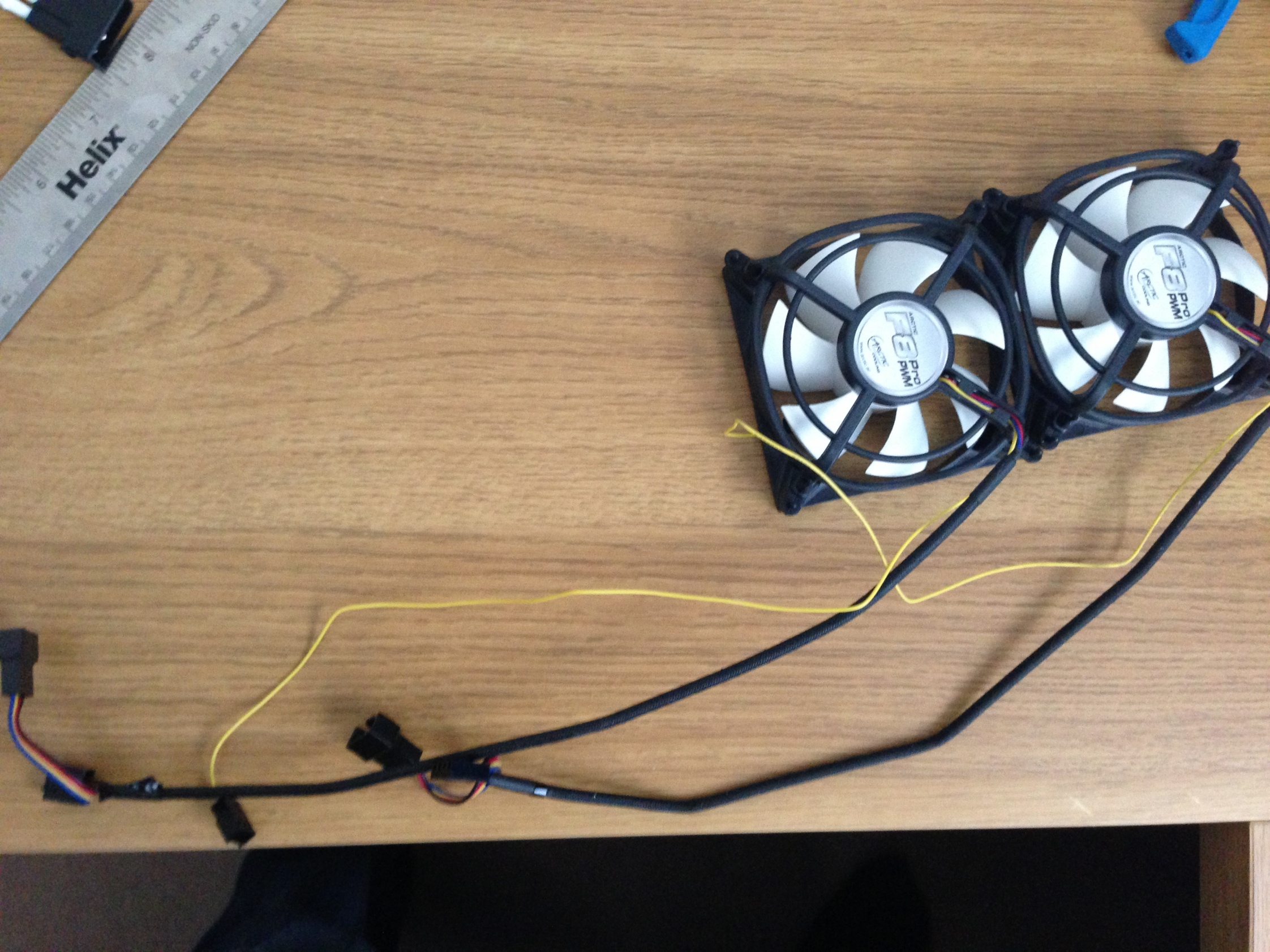
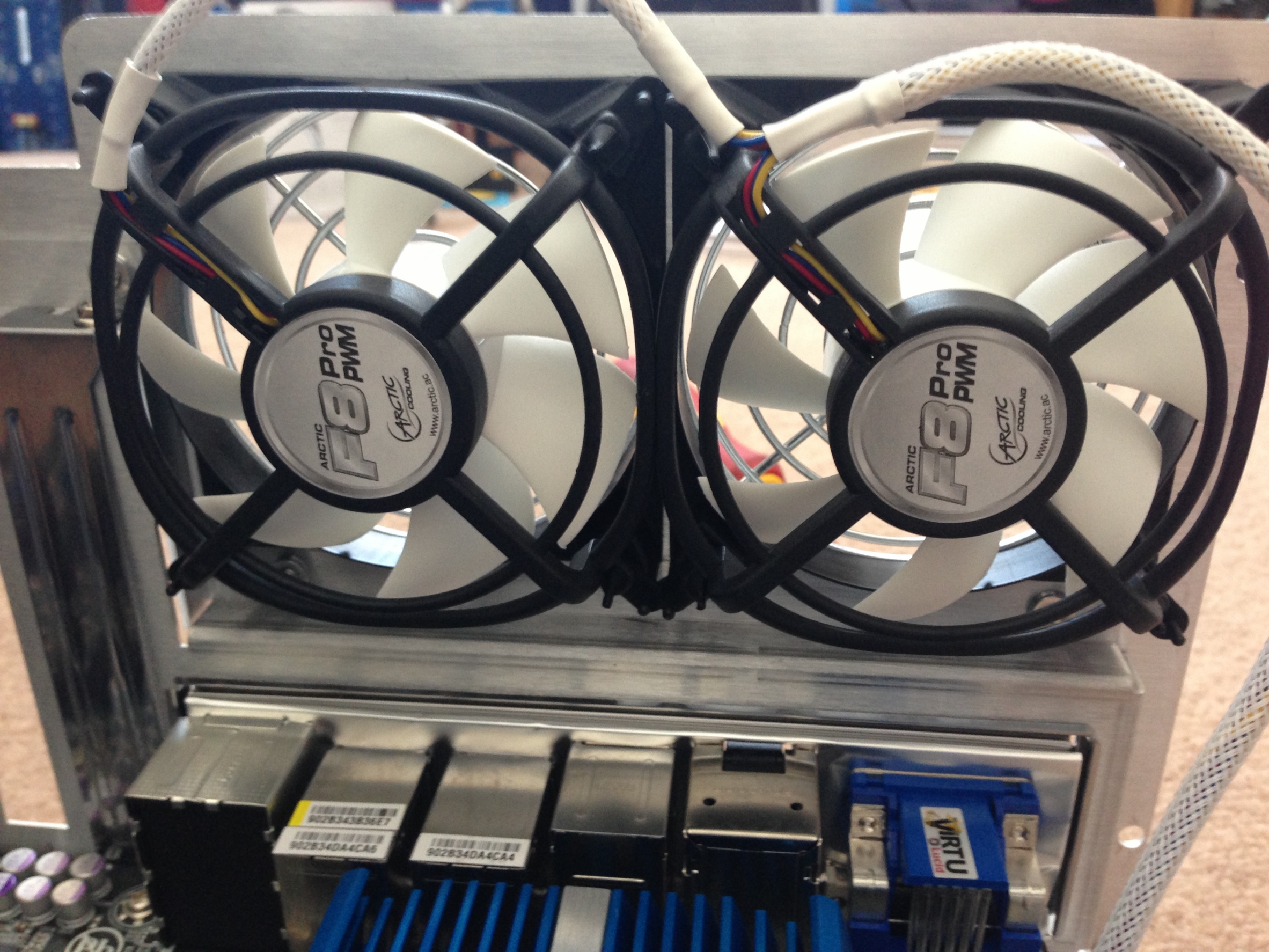
I ordered a large bag of goodies, 2 Arctic F8 fans, 2 Arctic F12 Fans, White cable braiding and some metal adhesive.

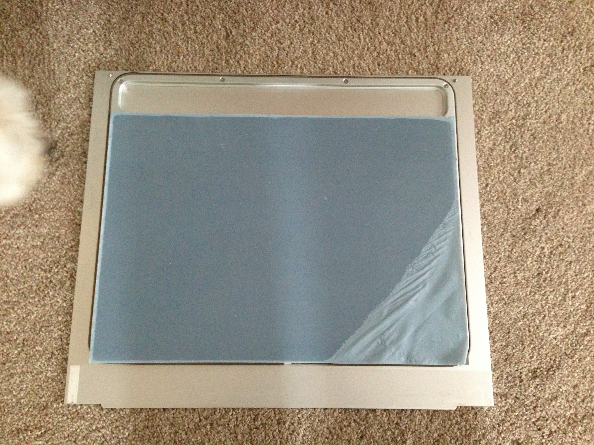
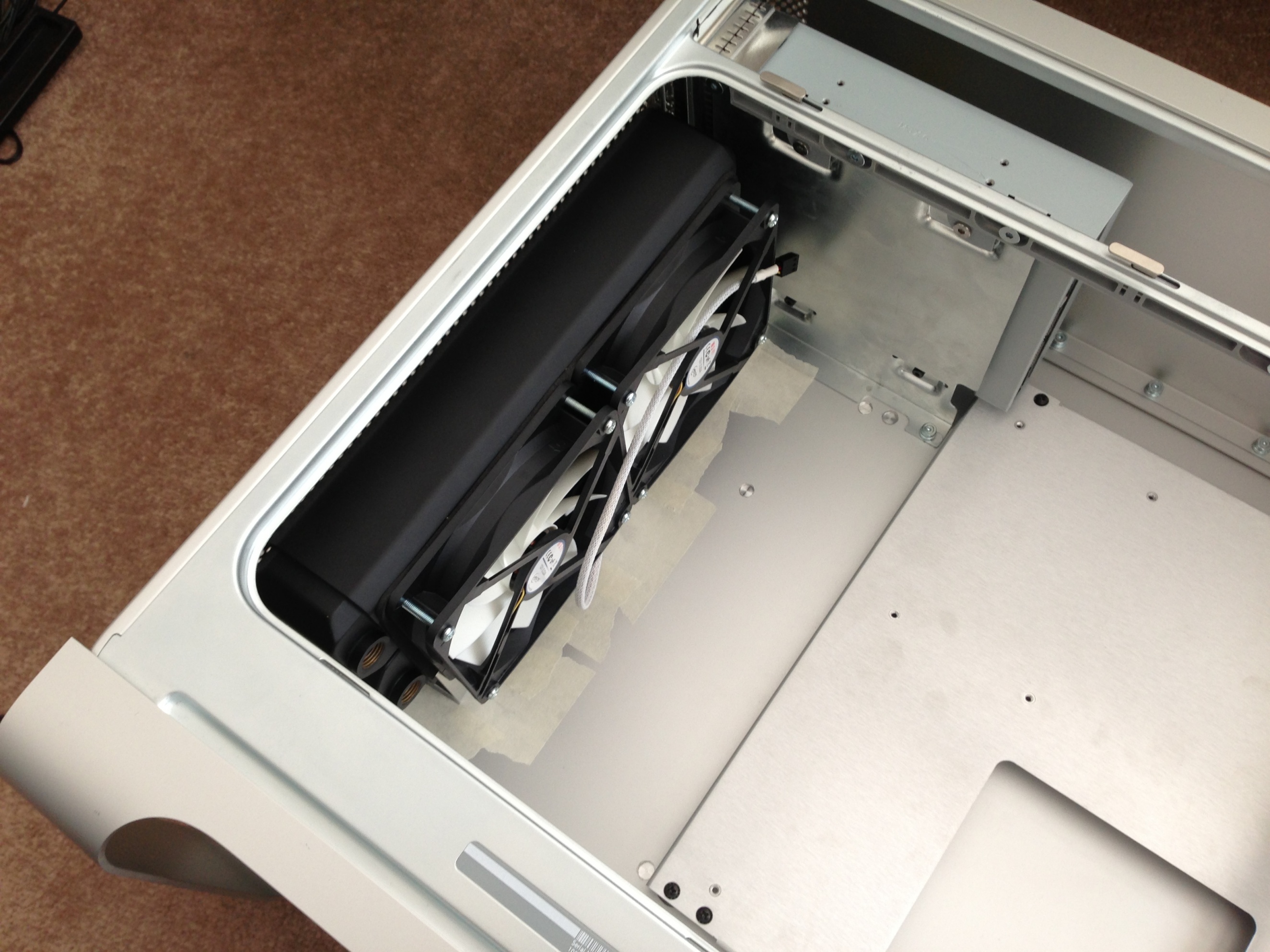
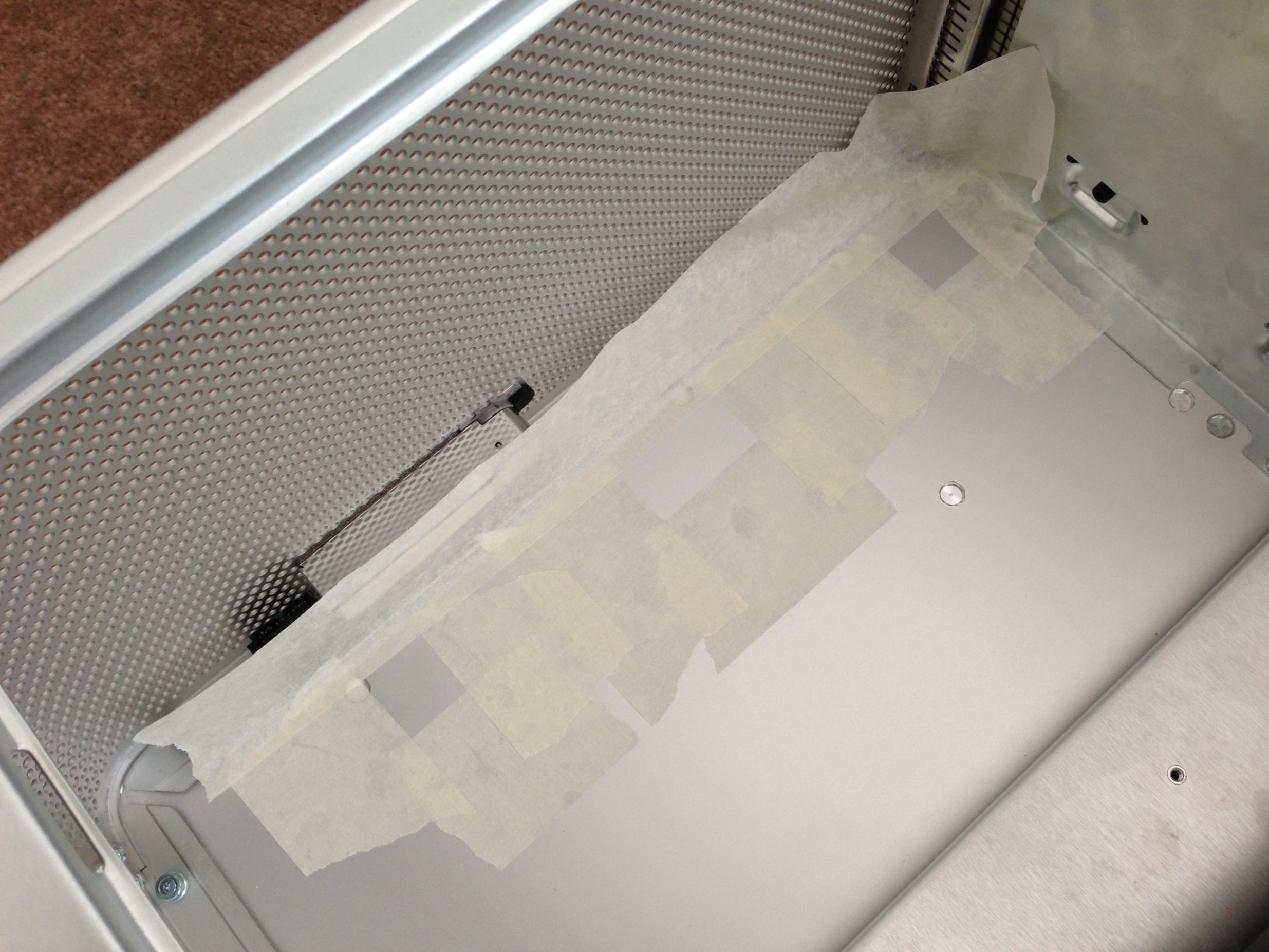
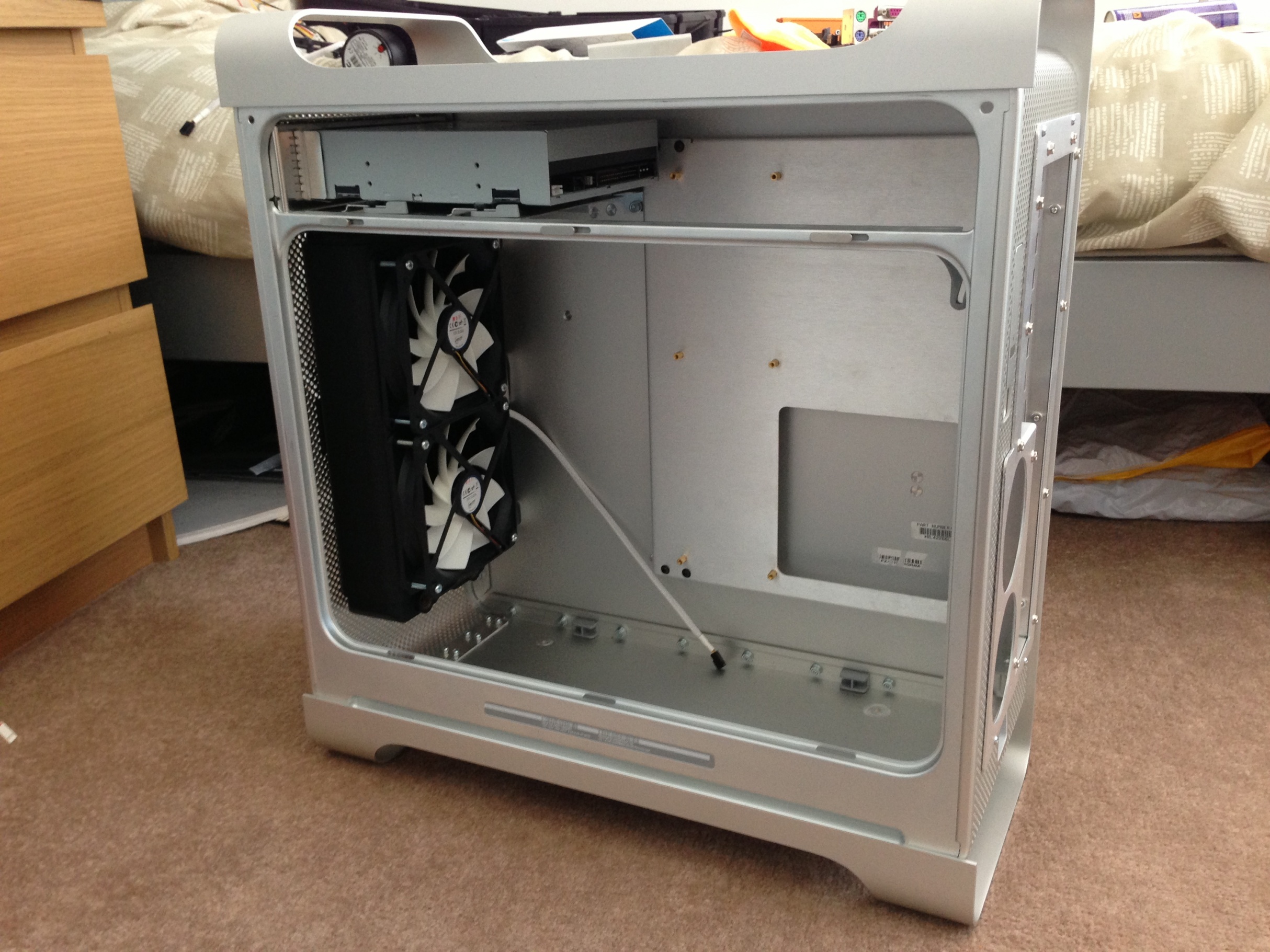
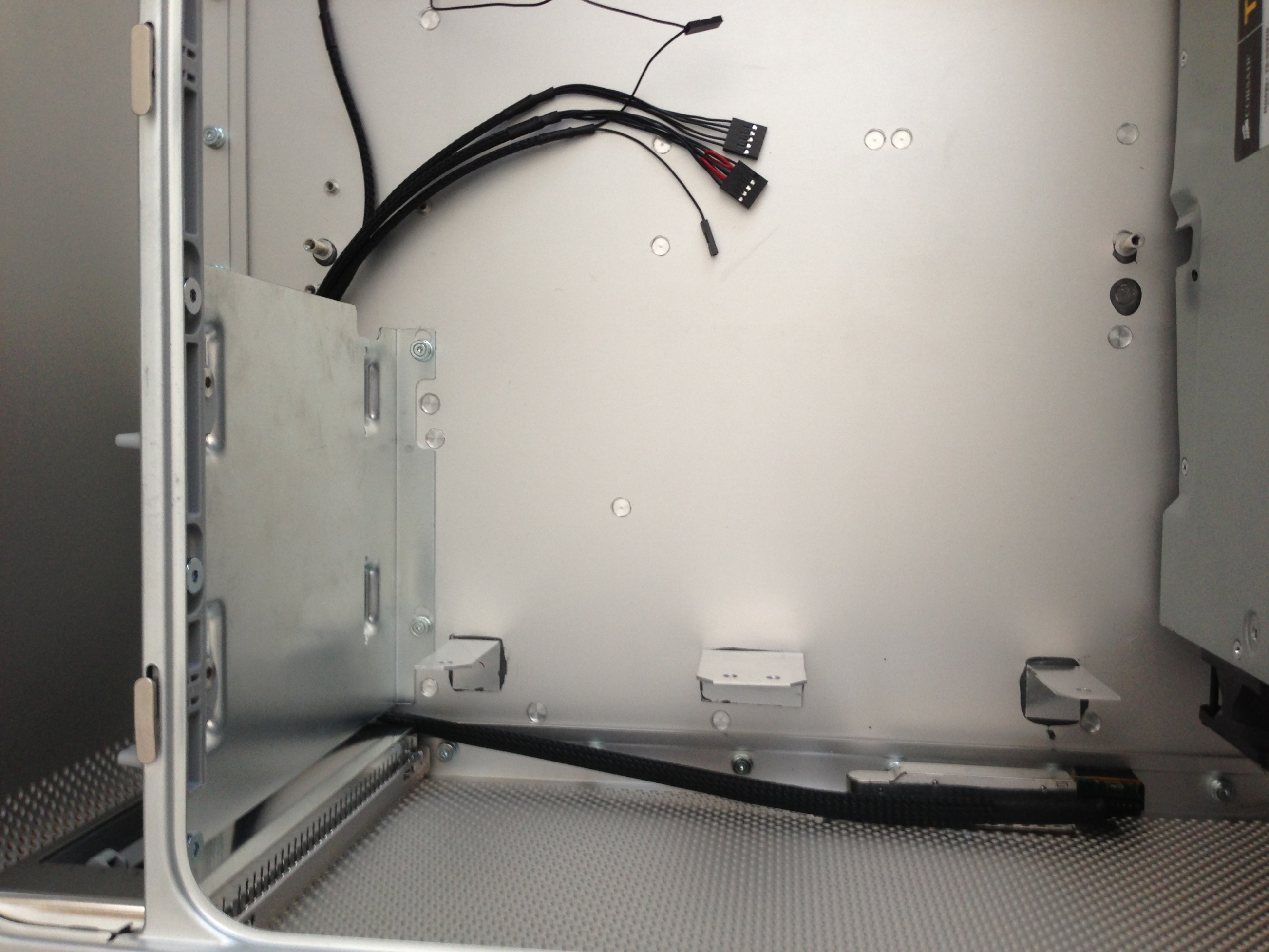
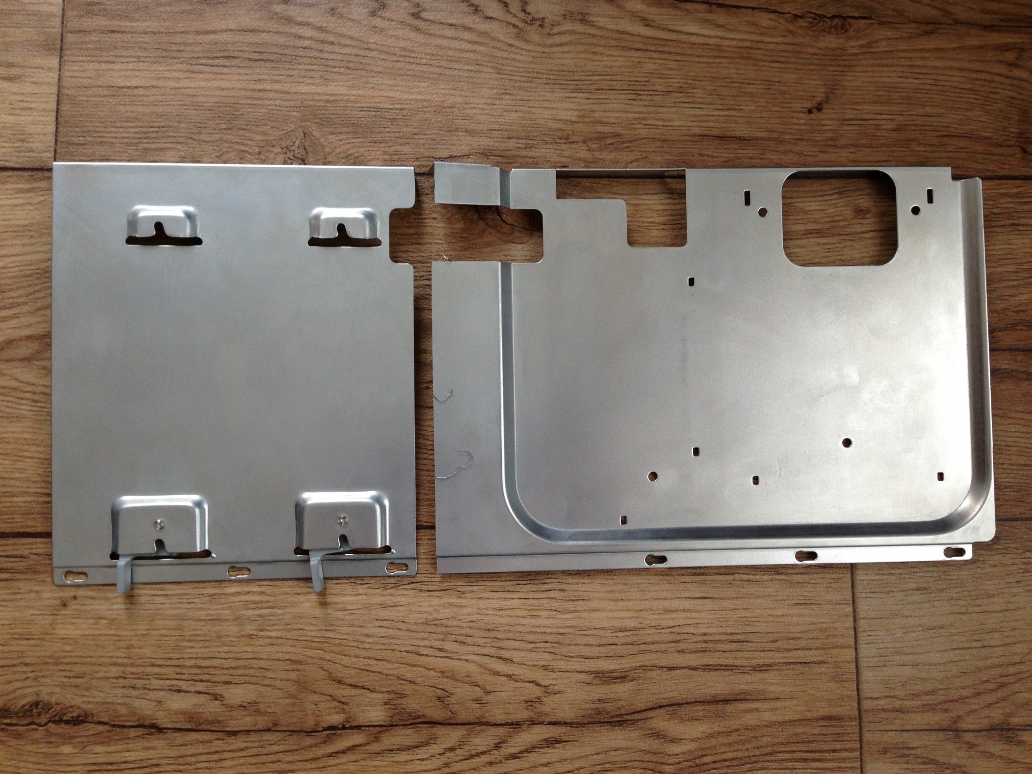
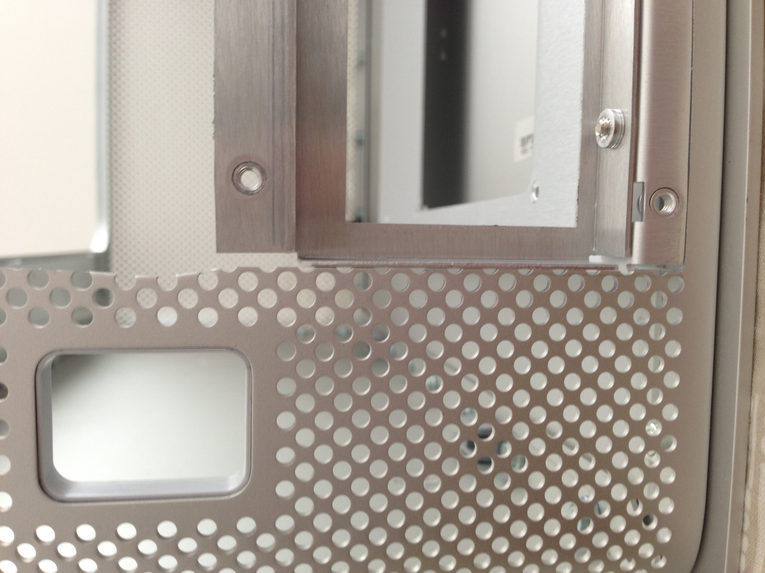
So i got straight onto carrying out the modification to the case...
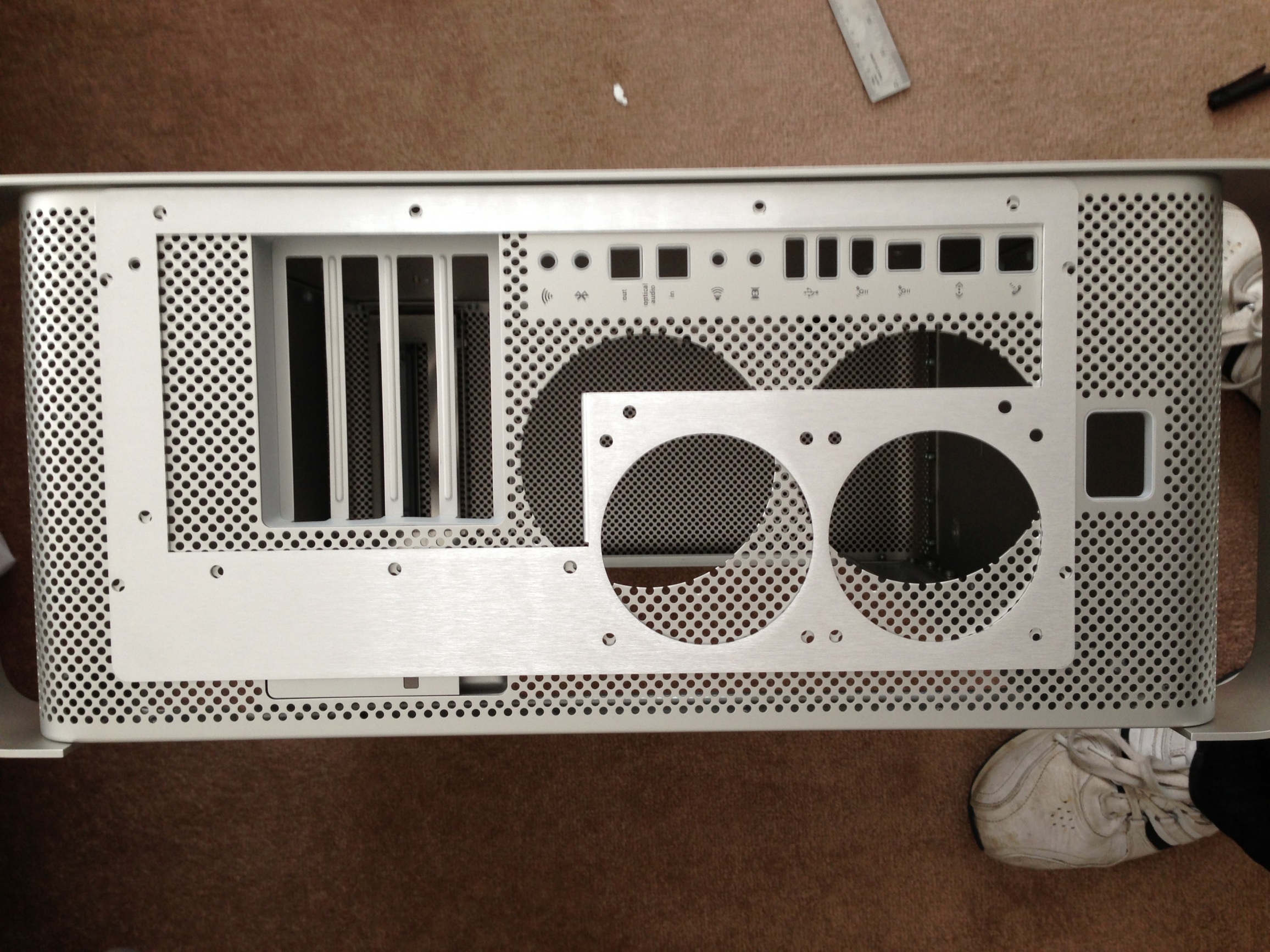


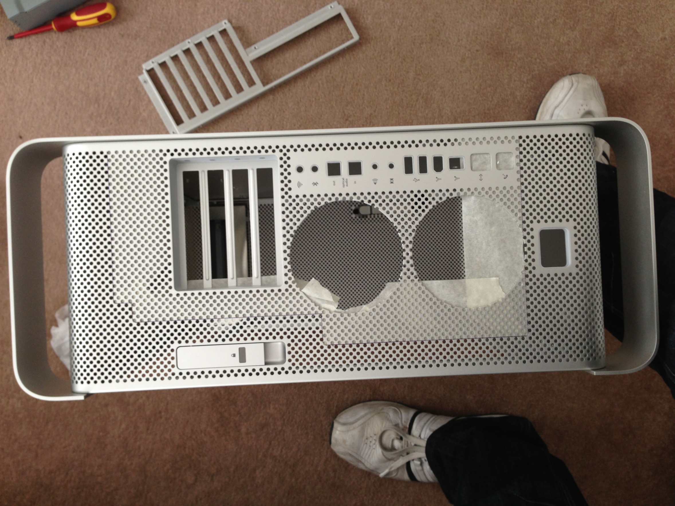
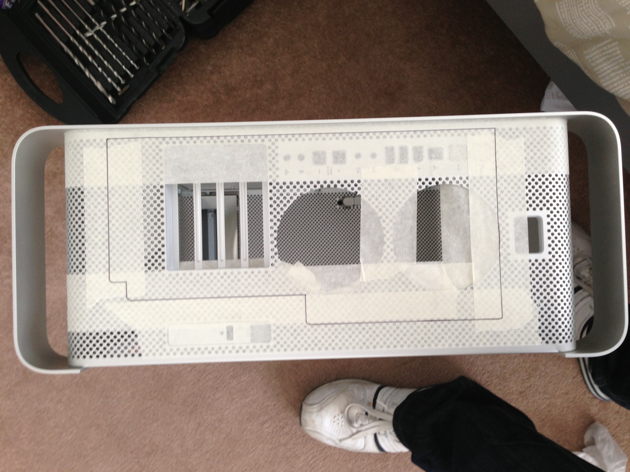
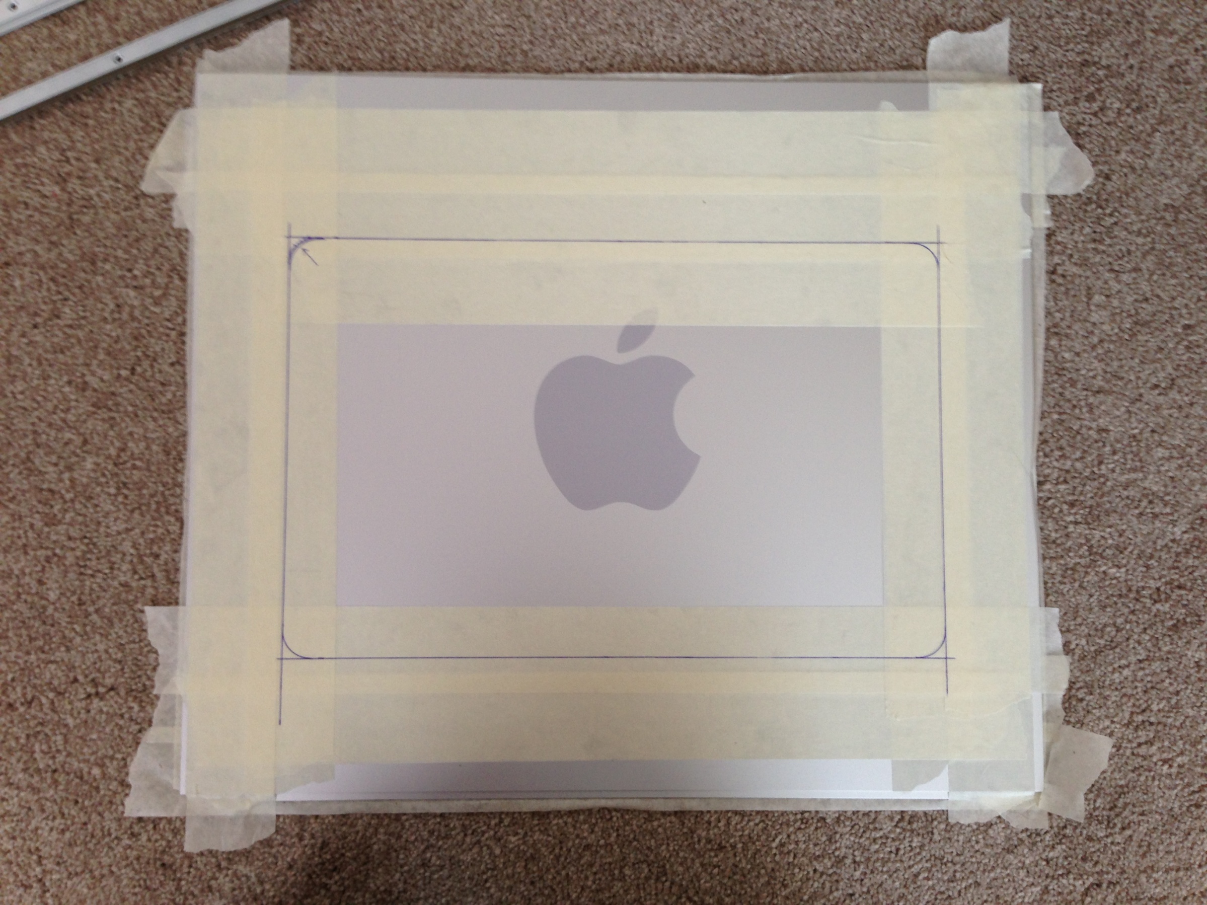
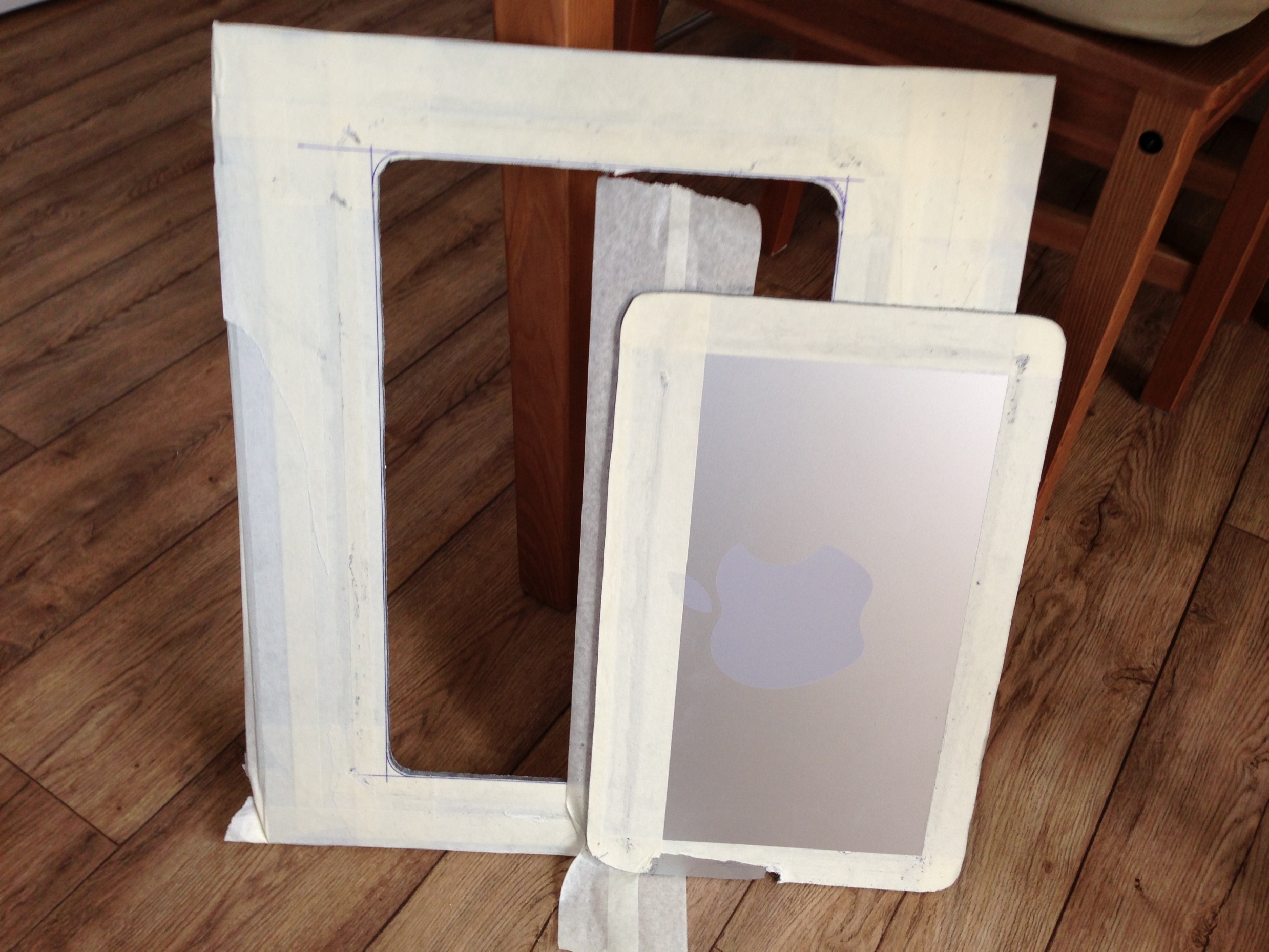
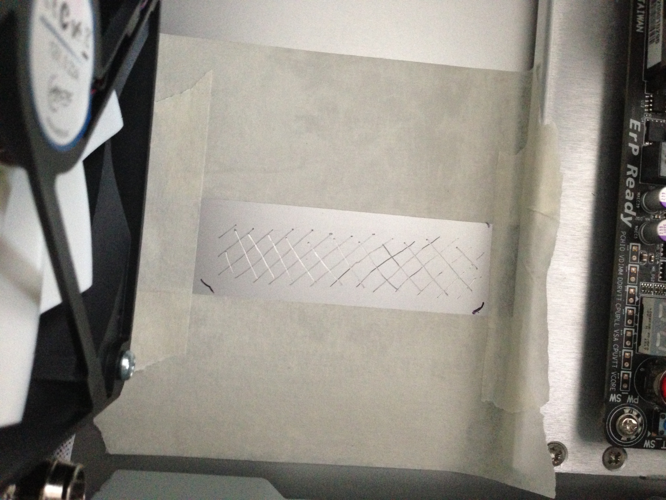
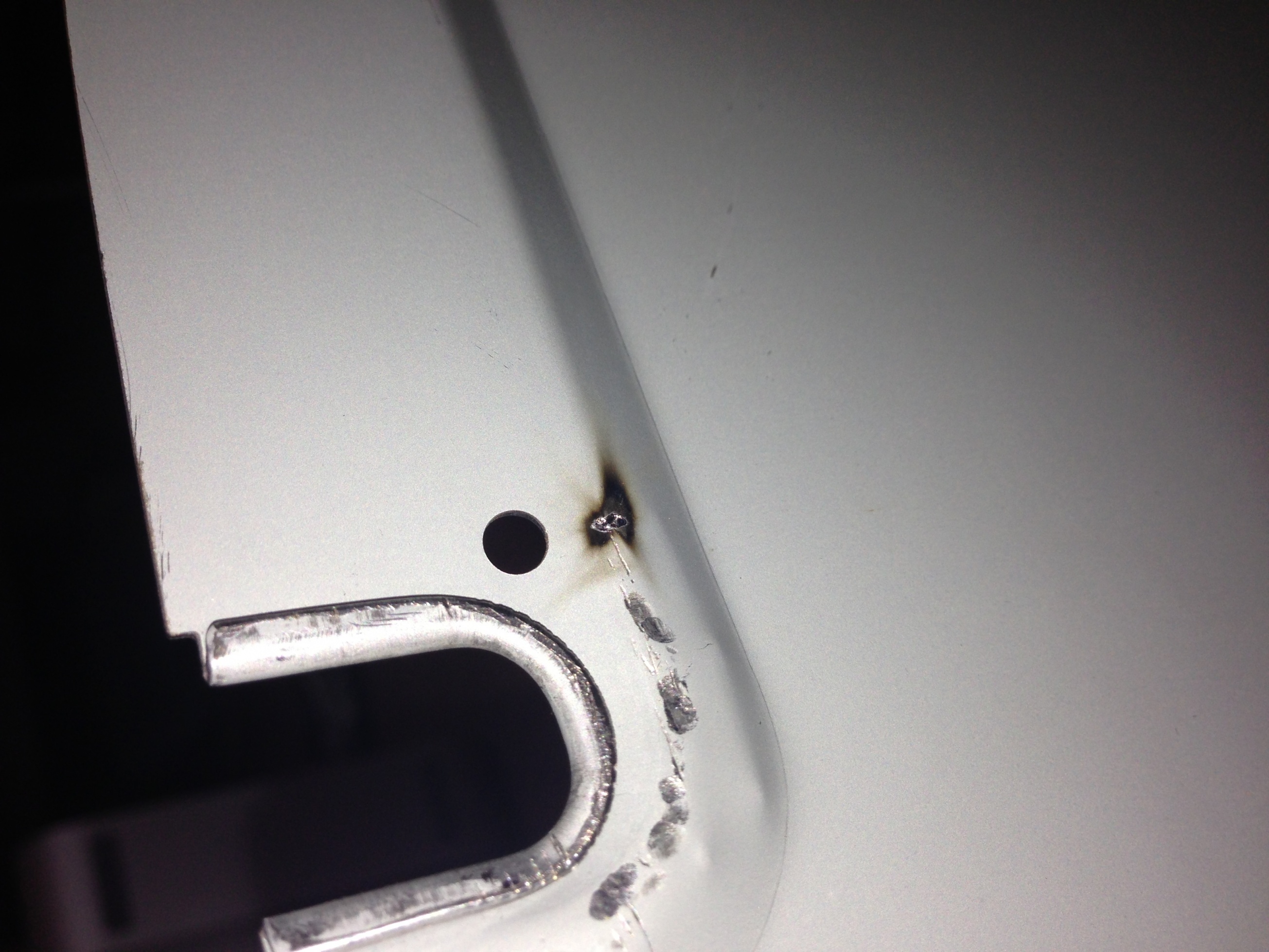
After lots and lots of measuring, then checking again just before i got my Dremel to hand, i started to cut the case.


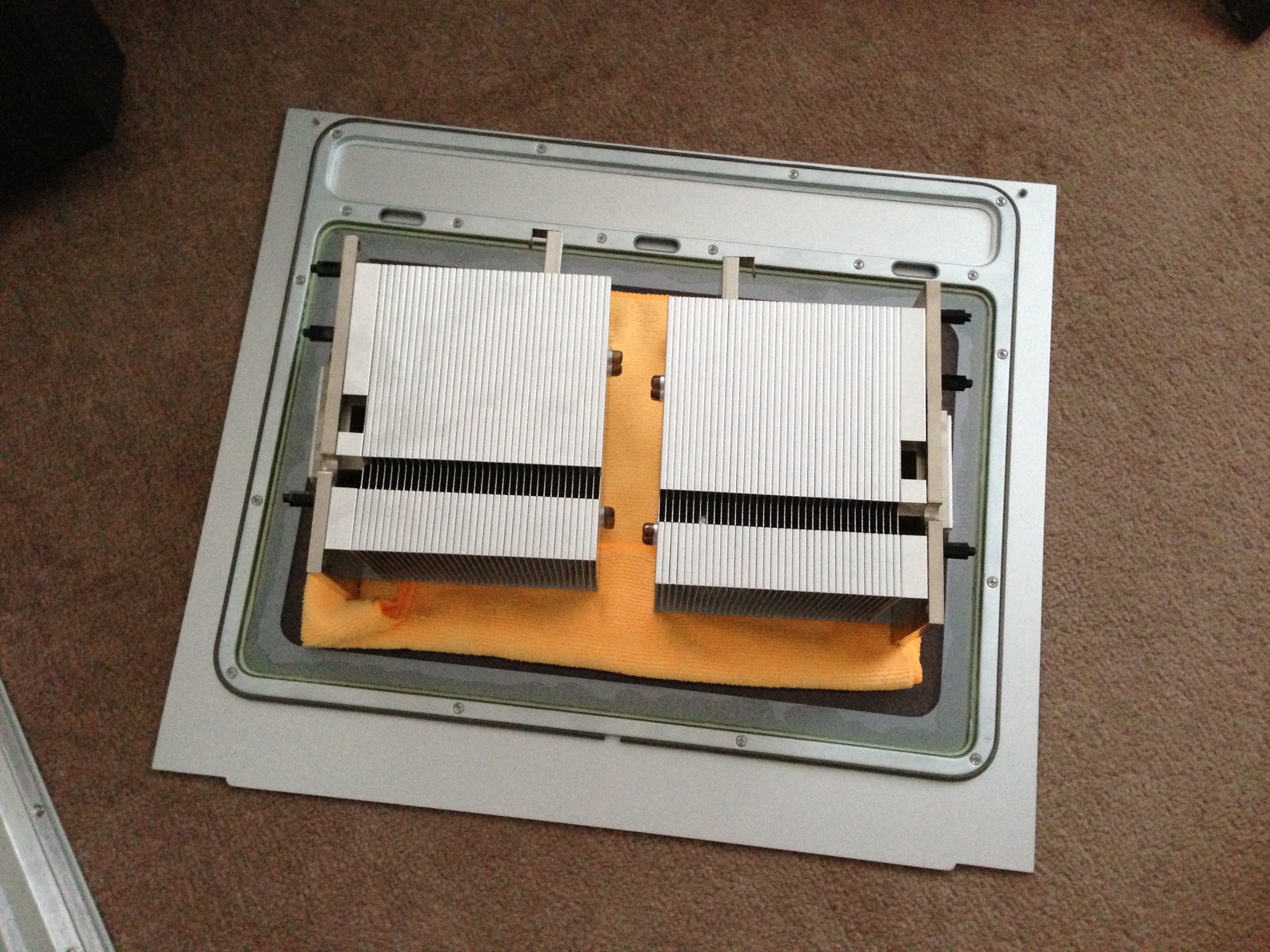
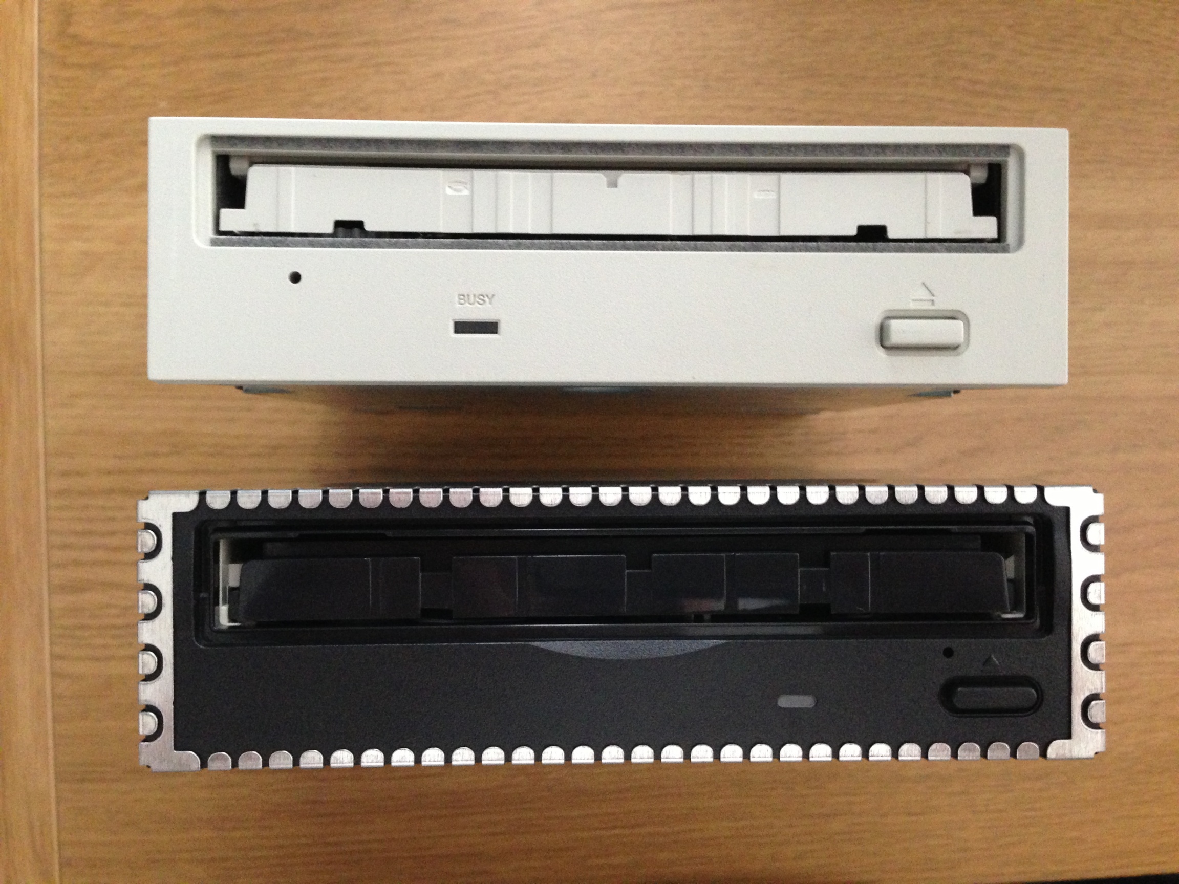
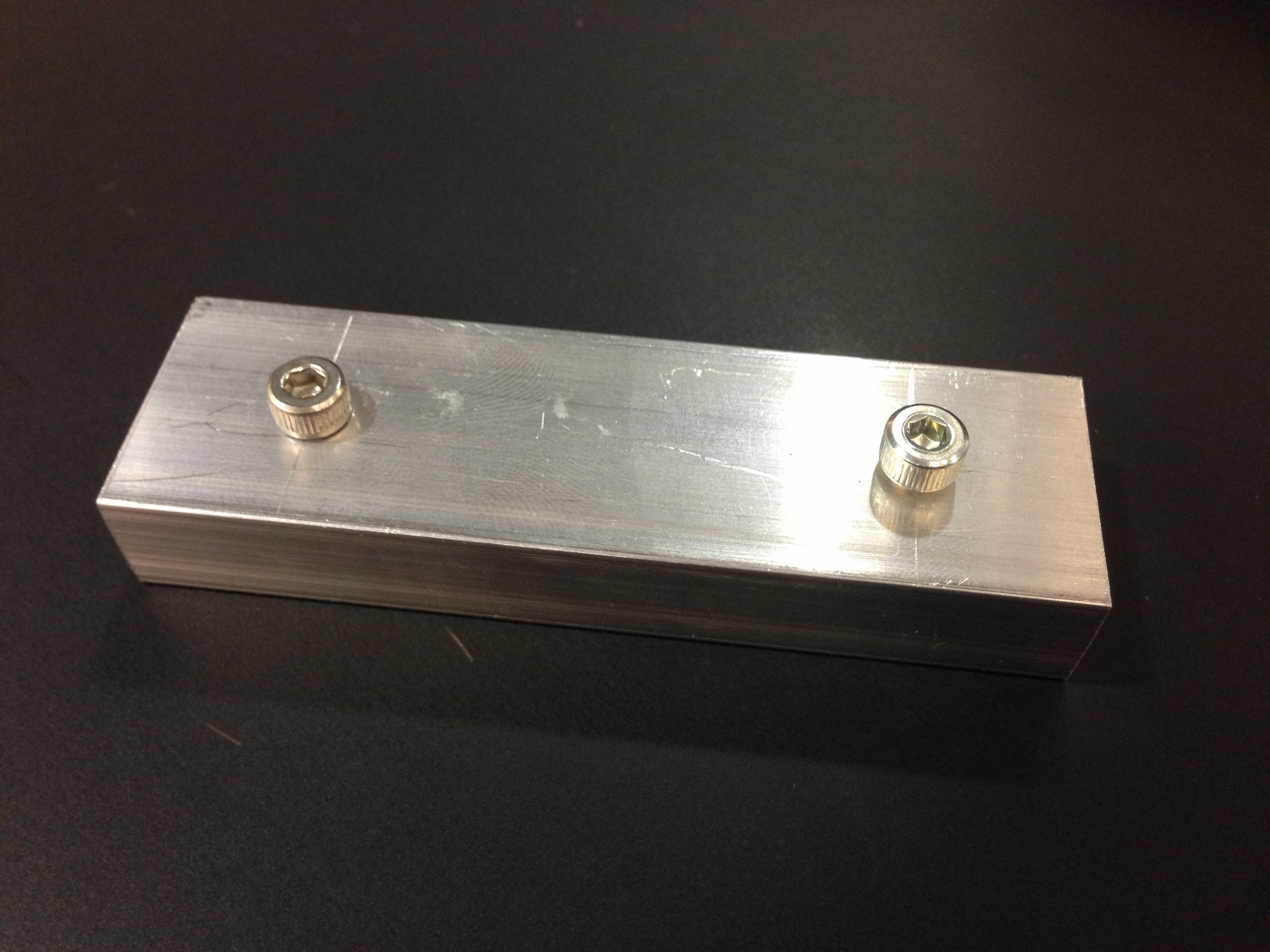
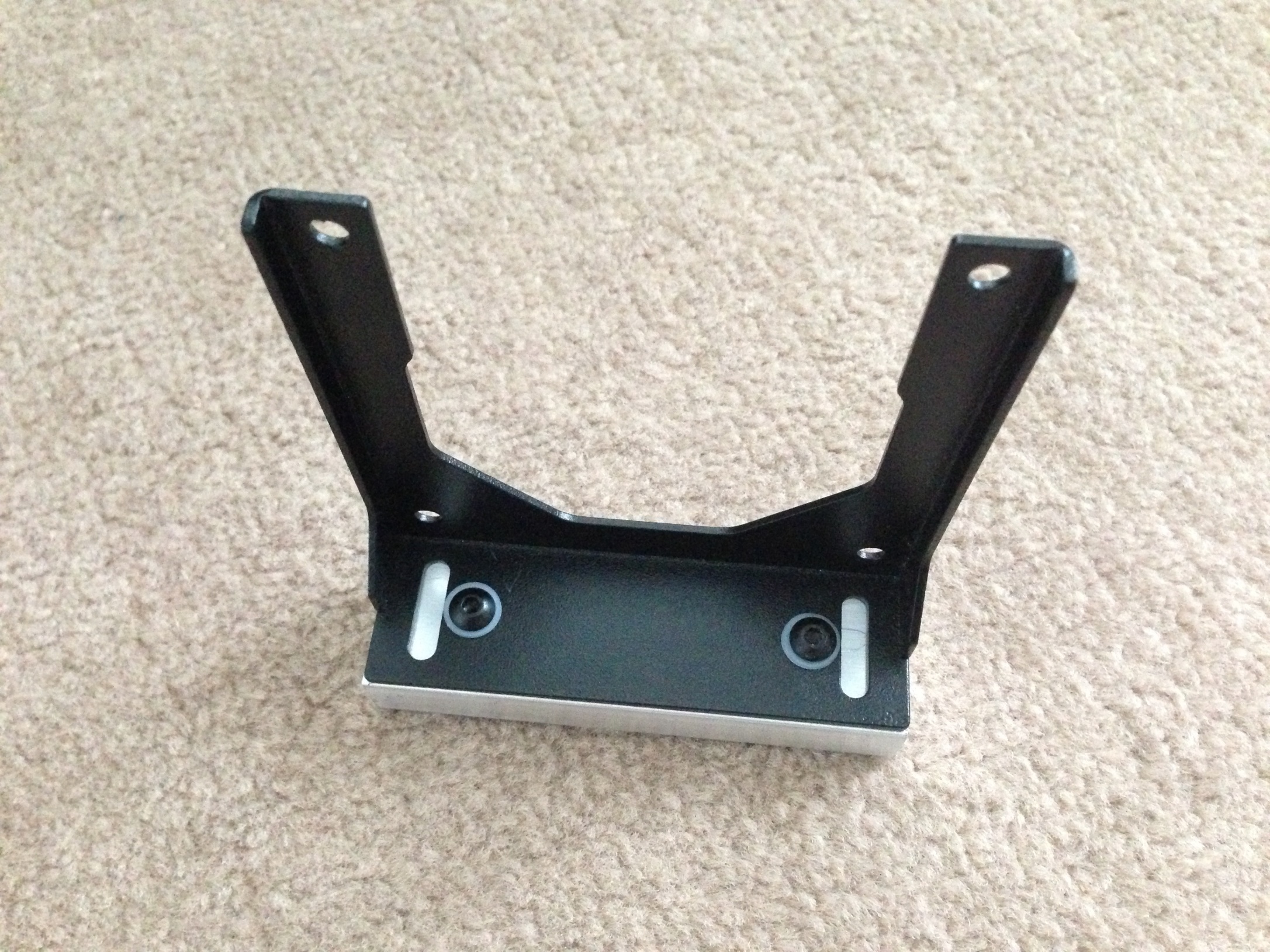
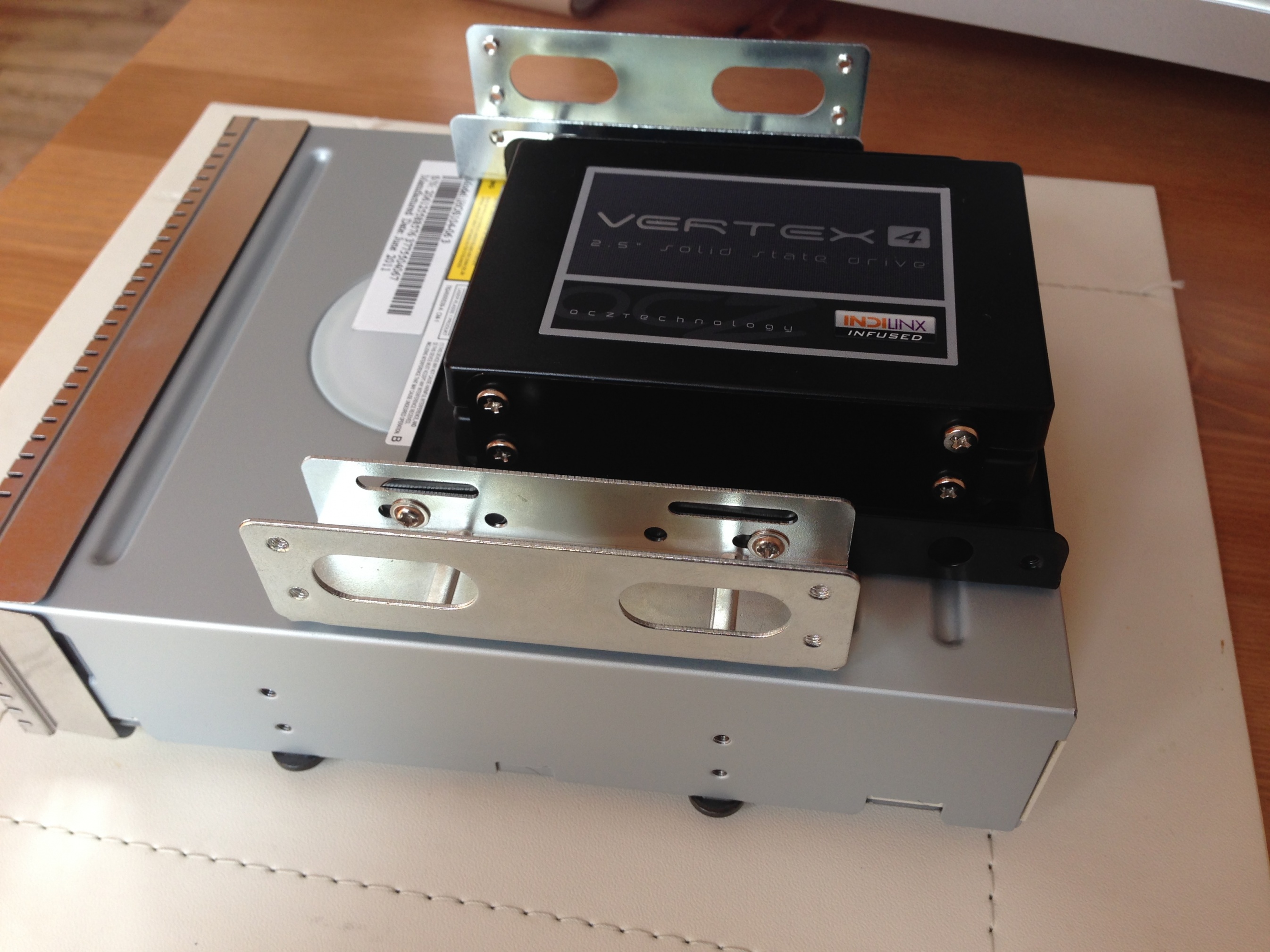
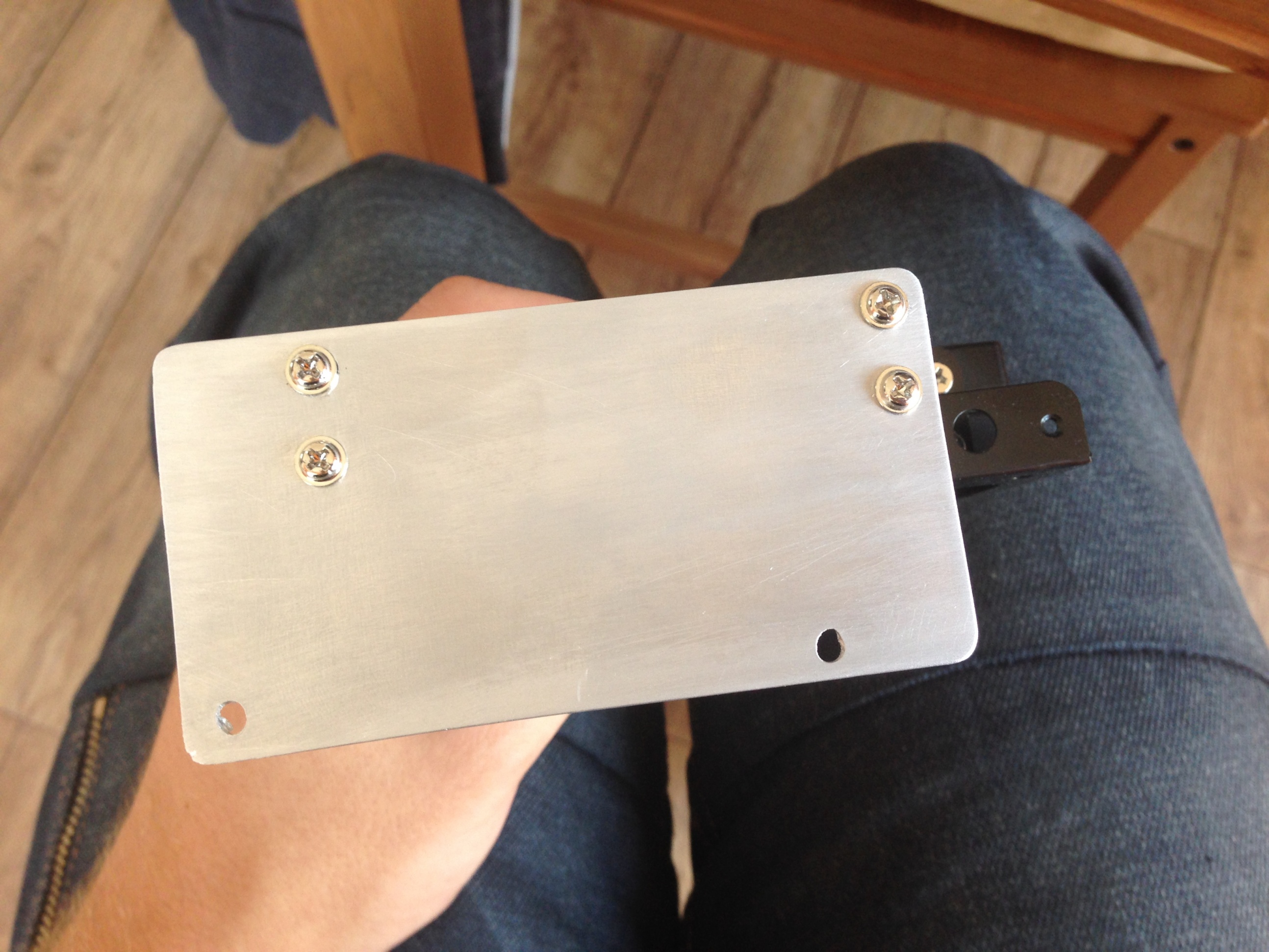
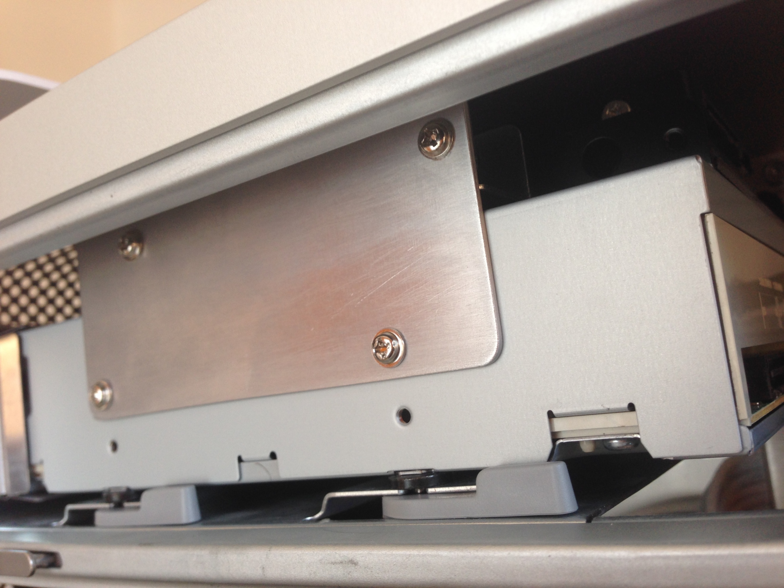
The cut turned out even better than i had hoped, so i started fitting the modified parts such as the modified optical drive mount i did earlier.
After many years of wanting to create 'my perfect computer' i finally took up the challenge of creating it. My aim was to create a Hackintosh that could run both OS's (primarily OS X), that had the feel of a Mac whilst having the essence of a gaming rig. It had to be visually pleasing both inside and out with water cooling and braided cabling. I seen many other mods on TonyMac Forums that gave me inspiration, One being minihack's and the other being brammee's.
This was the final result
Specifications
Intel Core i5 3570K 3.40GHz
Gigabyte Z77-UD5H
ASUS GTX 760 2GB OC
Avexir Core Blue 2666 8GB
2 OCZ Vertex 4 256GB
LG Blu-Ray Player
Corsair TX750M PSU
The Build
So, here is the Power Mac G5 Dual 1.86GHz 2004 Model, that i picked up in fully working order and in pretty much perfect condition (the reason i bought it). It came in its battered box and i picked it up from York, UK for £90.
I had a little bit of a mess on with it before dismantling it ready for modification, but then got right to work stripping it out.
Now it sat there for a few months as i was waiting to finish my university term, but whilst i was waiting i ordered the Mountain Mods motherboard tray as i had heard it was very well made.
So my plan was to utilize the original PSU and modify the cables, but having been there before (An iMac G3 Project), modding PSUs is not the easiest thing to do. I decided that it would be best to take the easier route and build a new PSU into it. So i removed and prepped it ready for a Corsair CX750M.
It was rotten inside that PSU! but anyways... I had planned to replace the PSU cover with a new bit of Aluminum as it will get rid of all the notches that were used for holding bits in its original state, but, unfortunately, as you will see later on it wasn't possible due to space constraints.
I ordered a large bag of goodies, 2 Arctic F8 fans, 2 Arctic F12 Fans, White cable braiding and some metal adhesive.
So i got straight onto carrying out the modification to the case...
After lots and lots of measuring, then checking again just before i got my Dremel to hand, i started to cut the case.
The cut turned out even better than i had hoped, so i started fitting the modified parts such as the modified optical drive mount i did earlier.
Last edited by a moderator:


")