
- Joined
- Jul 6, 2011
- Messages
- 172
- Motherboard
- Asus Z170i Pro Gaming
- CPU
- i7 6700k @4.6
- Graphics
- 980ti
- Mac
- Classic Mac
- Mobile Phone
Aug 4, 2013
So, Lets start this off at where I got my case. Ive been volunteering at a place called FreeGeek Twin Cities where they accept donations of computers, refurbish and the sell at an extremely low price. That being said, I'm going to try to get all my parts from there, but most of my parts may be a little outdated. Disclaimer: This will be a slow moving project, I expect completion time to be ~6 months
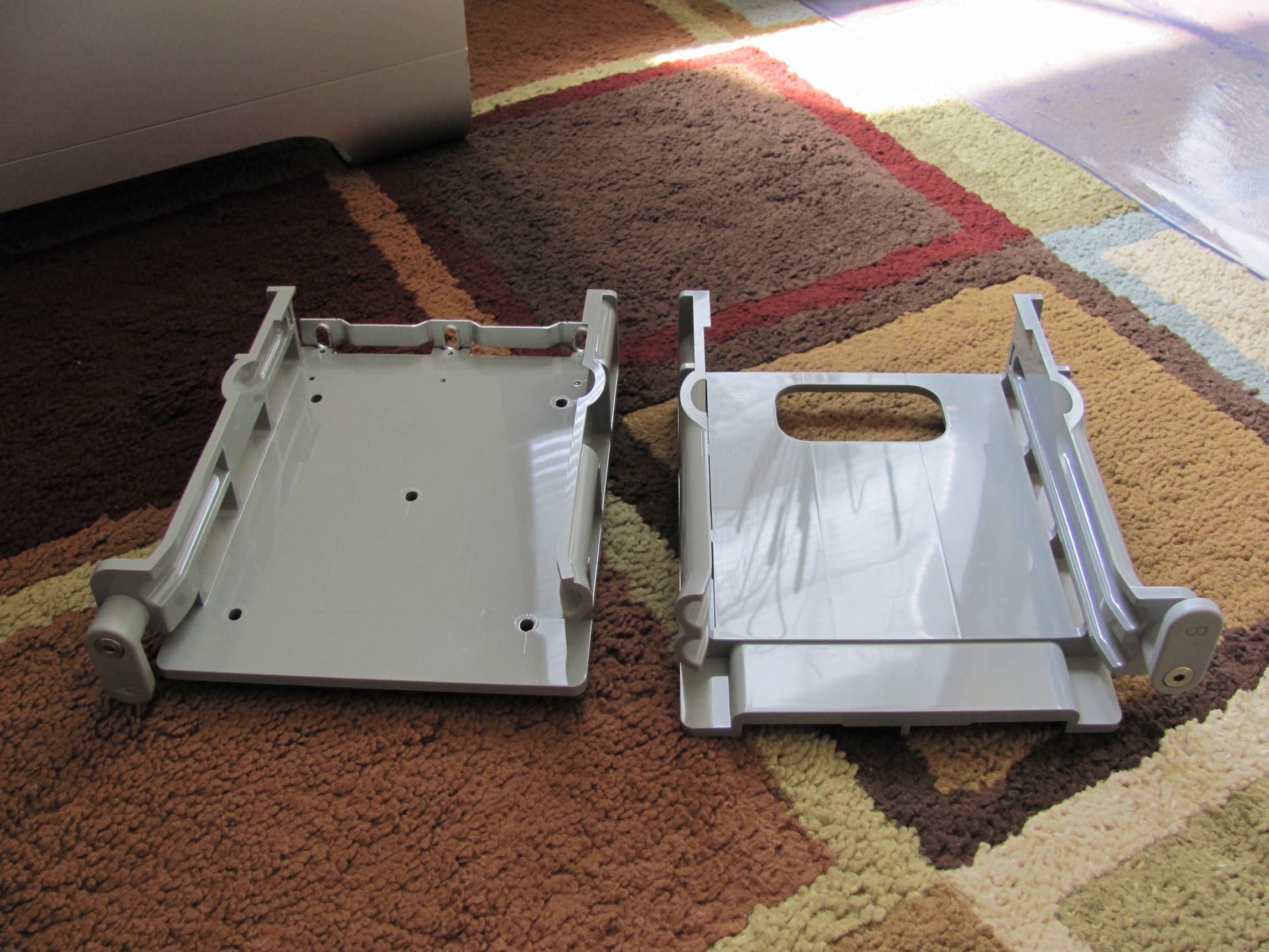
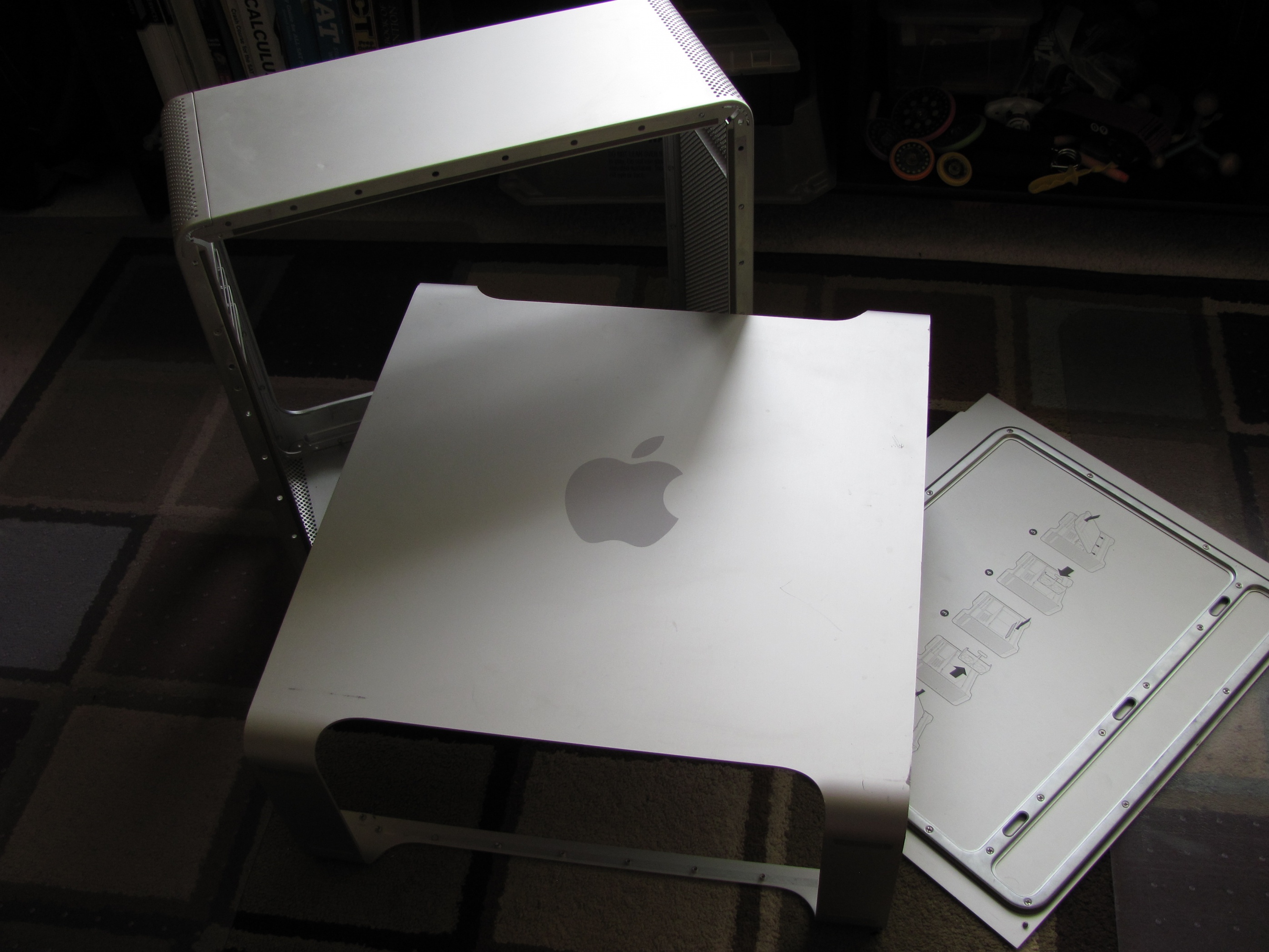
I scored on my G5 case as I got it for $10. It had the standard separator between the top and bottom, the two fans up top, and the hard drive cage. I started by taking out the separator and getting the cage out (explicit instructions here). So, it turns out that the HDD cage is separable in this model, so the bottom slot and top slot aren't attached.
My main focus of this build is aesthetics. No screwing steel pieces onto the case, and no ruining the look and feel of the G5. I even thought of flush mounting the back panel, but that might change. I might even get my case sandblasted, anodized, and then get the apple logo engraved onto the case again, if i have the budget.
Aug 6, 2013
I spent the last day further looking at other G5 mods, and came up with a cadded game plan in scale and with correct dimensions (PM me if you want a specific format (This implies that you are free to use and modify the design)).*

The motherboard in this picture is a GA-Z87MX-D3H, and is more or less eyeballed since I don't have one to take accurate measurements of. the components are in their right places though, so its reliable for wiring.
The plan is to go with an Intel LGA 775 mobo, and a Core 2 Quad Q6600 that i have in my possession, and upgrade from there. The PSU is located under the HDD Rack, and will be attached to the case via an L-shaped bracket on the front side as the wires come out of the right. I might just rip out a PSU mount from an old case and bend it to fit in the G5. The DVD Drive will be mounted as it is in a normal G5, but I will be cutting the separator plate to fit an ATX Motherboard, even though i don't plan on using one, and JB welding it to the back of the case.
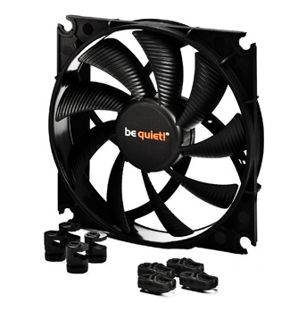
I should be able to buy a couple 92mm fans and 140mm fans from FreeGeek this weekend, but i eventually want to upgrade to Be Quiet 140 and 92mm Silent Wings 2 PWM fans.*
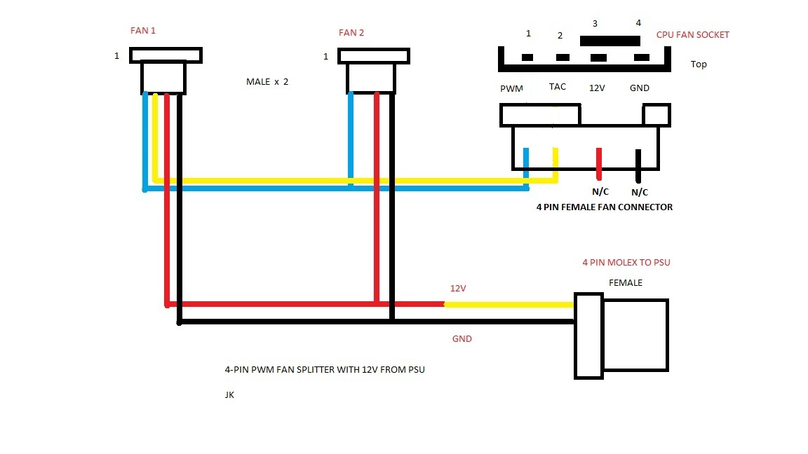
As for Fans connecting to the mobo, instead of going the commercially available solution, I decided to make it myself using this wiring diagram and a breadboard:
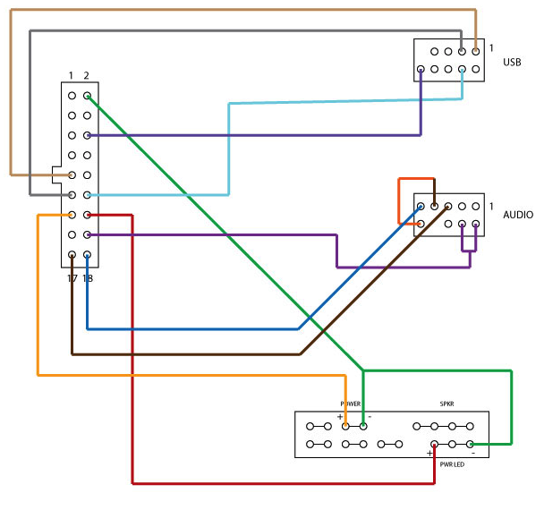
Since I love to work with wiring, I decided to make my own front panel header using a wiring diagram that I found on a forum thread almost a year ago.

Here's another one that gives you the option to do it without the firewire connection, and has the audio sense jumped so you can option select your audio source.
ModBot suggested that I use 24" cable for the front panel header, so I decided to get these: Pre Crimped Wiring , since I don't have a crimper.
The little 1" by 1" rectangle on top of the Front panel module is this as well as a reset button connected to the motherboard.
The only thing that hasn't been finalized is the HDD rack. I might end up shelling out $30 on the SansDigital HDD Rack and remove the fan or build my own out of aluminum u-channel and 90 degree channel.
August 7, 2013
So I figured that I can get a macbook IR receiver, and Bluetooth module working through a USB Header.
Can't do much until I get my parts...
Aug 11, 2013
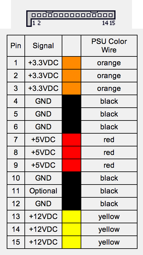
So, I just figured out that I could integrate my fan controller that I've wanted to do on a stripboard, and an Apple bluetooth module on the same PCB using the 12v rail for the fans, and the 3.3v rail for the bluetooth module. SATA has all three voltages on it, so I need to find a male SATA connector to use for the purpose of the PCB. The pinout for SATA Power:
I also want to have an internal speaker with a solid state chime that goes off when the computer starts up, something like this. I might even look into adding an array of the speakers and setting up a proper internal speaker system, although, noting beats a pair of finely tuned earphones. While we're on the topic of internal additions, i might add one of those card reader things that go on the front of some OEM and "classic" pc cases in the topmost 3.5" HDD bay.
I also found a great guide on Dozuki for people interested in taking all the components out of the case and having it anodized/ powder coated/ spray painted.
As a further note for today, I came up with ideas to flush mount my back panel. Ideas include using 20mm strips of aluminum, glueing them to the back, and drilling out 2mm holes in the exact pattern like this as well as having that 20mm wide aluminum laser cut and fitting exactly (more expensive [DUH!]).
August 11, 2013
Where do I start, So much has happened today.*
Parts
More Detail:
Work
So far, I’ve bundled 3 wifi antennas to the wifi card and insulated them all.
Desoldered the unfortunate solder joint that HP put in between one of the sets of antennas that I got.
And last and not least, made a temporary connection from the Bluetooth module to USB. I know it needs 3.3v and I’m giving it 5v. Anyone have and idea how to see if it’s working on Mac OS X? My MBPr already has bluetooth so that’s the only bluetooth related device hat shows up. Do I have to restart or something of those likes?
Anyway, back to the module...
I cut the connector wire, and I found that the two nonstandard colors in one of the cables was green and yellow, while the other had a light green and pale yellow. as far as the wiring diagram goes, the green connects to the yellow and the white connects to the green. The module itself has nothing to be changed. I stripped the four wires and connected them the right way to the USB cable that I had lying around and... nothing.
I can't get it to friggin work with my MBPr! I even tried switching the two data wires.
August 12, 2013
I was doing some research and ran across this. I's quite interesting and I might end up just replacing the stators for the two 92mm fans in the back.
Disclaimer: The following sketches of back panel parts are not exact and may be off by +- .5"
I sketched the two parts that make up my backplate, and finalized them with Minihack. Unfortunately he wouldn't be able to get them cut out until at least September 14th. My design has two parts, the hook and the blade, just kidding. Anyway, it has two components to it and they fit together in a steplike design. the top plate will be flush to the outside of the case while the bottom part secures the top part to the case. The two plates will be glued together and the bottom plate will be screwed into the case with (hopefully) the same screws as the ones used to fit the fan shroud.
August 14, 2013
Today, considering the fact that if I used the original G5 PCI bracket, there would be a 3/4" gap between the IO Shield and the IO ports, I've decided to just order an ATX conversion kit from The Laser Hive, or fabricate one myself out of old cases, and laser cut Aluminum. I'm still going to try to make the backplate flush, and I will still use the dual 92mm shroud that is standard on the G5.
I also took apart the case today. I found this guide for people confused about how to do this.I had to take out circa 100 screws and nuts, then I realized that the two parts of the inner G5 are riveted together, and put the nuts back to hold that in place. I also couldn't get one screw from the bottom door side of the case, and ended up stripping it. Luckily the mount (threaded female part) was fused into the case just like the motherboard mounts, and after ~30 minutes of struggling with it, I just popped it off. I then took the sharp part of my file and punched the screw out of it's hole. I'm happy to say, there was no damage in to the case except taking a bit of aluminum off the inside of the case (I don't really mind) and the stripped screw (of course).
I also sanded down the little mount that I tried to pry off and failed at. the best way, I found was to take a piece of paper, put it on top of the part you want to file and start filing. The file will cut through the paper and file only the part and not scratch any of the other parts of the case.
Aug 22, 2013
Sorry I haven't updated in more than a week, but I was busy with other things.
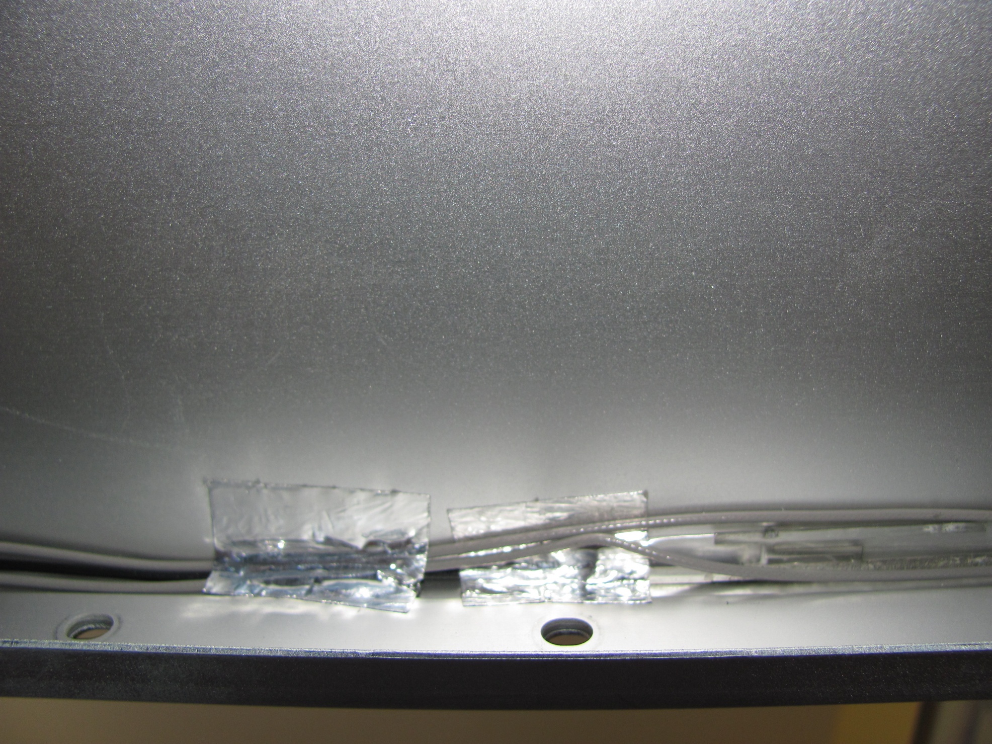
First of all, I placed the 3 wifi antennae in the case on the top part of the solid aluminum.
Turns out, the signal is really weak, and I couldn't see my own wireless network, but I ended up picking up my neighbors. So, after that blunder, I decided to get rid of the current arrangement, and decided that I would get that sorted out after I get an acceptable mPCIe to PCIe x1 converter (I'm looking for a cheap one without antennas).
About the 19th, I borrowed a Dremel 300 from my First Robotics team.
Next, I cut the DVD plate to the correct dimensions. the little strip is because the locking mechanism and the metal bar it attaches to have a slight gap in the middle that keeps the latch from clicking shut.
I almost threw out the rest of the metal plate, but a family member (Thanks Mom!) decided to save it just in case I needed it. Turns out I did need it. I originally decided to cut the excess off and bend the rest and have the PSU screw in, but then I released that the screws would be inaccessible, and so revised my design by cutting a little more off. Then I thought about using magnets to mount the PSU, and the third design I came up with has the ability for PSU position customization. I attached the magnets to the plate, and the plate to the case using JB Weld. I totally forgot that JB Weld has steel filings until I pit it on a magnet, and it started spreading by itself. Oops...
I originally had 3 easy attach cutting wheels for metal, but after the cutting and re-revising of the PSU plate, I ran out of them.
I decided not to use the original G5 front panel cable because I thought it was disorganized. Instead, I opted for a (mini) IDE style cable that I found (currently used for the serial and parallel headers on newer motherboards). I liked this because the number of the cables went up in ascending order instead of being intertwined and being split from the origin. I tested to see which done was pin 1, and after I found it, I aligned it to the G5 pin 1. I will wire this up to standard Firewire, USB, and Audio headers as well as power button and light.
Here's the final plan for placement. The single HDD signifies the rack since I don't have one.
August 23, 2013
Today's progress was minimal. I figured out that a stock LGA775 Intel fan could fit instead of a 92mm fan into the fan grill, and also had a spark about using a screw-in power plug in a pop-in socket.
I first dremeled (yes, I got more metal cutting wheels for the dremel) off the standoffs that existed to attach the fan to the stock heatsink, and filed it to be flush (Sorry, I forgot to take "before" pictures). I will later attach the fan to the stock apple fan grill tomorrow as I don't feel like firing up the hot glue gun.
I then cut off the two pieces that enables the power plug to screw in, and then filed it until it had a snug fit in the G5 socket (Sorry, I forgot to take "before" pictures). I will also hot glue this tomorrow as it's late and I'm lazy. I also need to do the wiring tomorrow.
The plans for tomorrow are to get another LGA775 fan and a HDD rack that will fit in my case. I also need to get some perspex for the front fans that I'll be putting in later, as well as an incorporated case speaker that (hopefully) does the chime.
August 25, 2013
Minor Update: apparently I finished
I only have one picture of the final build apparently, and i put it on facebook so its gonna be really compressed.
So, Lets start this off at where I got my case. Ive been volunteering at a place called FreeGeek Twin Cities where they accept donations of computers, refurbish and the sell at an extremely low price. That being said, I'm going to try to get all my parts from there, but most of my parts may be a little outdated. Disclaimer: This will be a slow moving project, I expect completion time to be ~6 months
I scored on my G5 case as I got it for $10. It had the standard separator between the top and bottom, the two fans up top, and the hard drive cage. I started by taking out the separator and getting the cage out (explicit instructions here). So, it turns out that the HDD cage is separable in this model, so the bottom slot and top slot aren't attached.
My main focus of this build is aesthetics. No screwing steel pieces onto the case, and no ruining the look and feel of the G5. I even thought of flush mounting the back panel, but that might change. I might even get my case sandblasted, anodized, and then get the apple logo engraved onto the case again, if i have the budget.
Aug 6, 2013
I spent the last day further looking at other G5 mods, and came up with a cadded game plan in scale and with correct dimensions (PM me if you want a specific format (This implies that you are free to use and modify the design)).*
The motherboard in this picture is a GA-Z87MX-D3H, and is more or less eyeballed since I don't have one to take accurate measurements of. the components are in their right places though, so its reliable for wiring.
The plan is to go with an Intel LGA 775 mobo, and a Core 2 Quad Q6600 that i have in my possession, and upgrade from there. The PSU is located under the HDD Rack, and will be attached to the case via an L-shaped bracket on the front side as the wires come out of the right. I might just rip out a PSU mount from an old case and bend it to fit in the G5. The DVD Drive will be mounted as it is in a normal G5, but I will be cutting the separator plate to fit an ATX Motherboard, even though i don't plan on using one, and JB welding it to the back of the case.
I should be able to buy a couple 92mm fans and 140mm fans from FreeGeek this weekend, but i eventually want to upgrade to Be Quiet 140 and 92mm Silent Wings 2 PWM fans.*
As for Fans connecting to the mobo, instead of going the commercially available solution, I decided to make it myself using this wiring diagram and a breadboard:
Since I love to work with wiring, I decided to make my own front panel header using a wiring diagram that I found on a forum thread almost a year ago.
Here's another one that gives you the option to do it without the firewire connection, and has the audio sense jumped so you can option select your audio source.
ModBot suggested that I use 24" cable for the front panel header, so I decided to get these: Pre Crimped Wiring , since I don't have a crimper.
The little 1" by 1" rectangle on top of the Front panel module is this as well as a reset button connected to the motherboard.
The only thing that hasn't been finalized is the HDD rack. I might end up shelling out $30 on the SansDigital HDD Rack and remove the fan or build my own out of aluminum u-channel and 90 degree channel.
August 7, 2013
So I figured that I can get a macbook IR receiver, and Bluetooth module working through a USB Header.
Can't do much until I get my parts...
Aug 11, 2013
So, I just figured out that I could integrate my fan controller that I've wanted to do on a stripboard, and an Apple bluetooth module on the same PCB using the 12v rail for the fans, and the 3.3v rail for the bluetooth module. SATA has all three voltages on it, so I need to find a male SATA connector to use for the purpose of the PCB. The pinout for SATA Power:
I also want to have an internal speaker with a solid state chime that goes off when the computer starts up, something like this. I might even look into adding an array of the speakers and setting up a proper internal speaker system, although, noting beats a pair of finely tuned earphones. While we're on the topic of internal additions, i might add one of those card reader things that go on the front of some OEM and "classic" pc cases in the topmost 3.5" HDD bay.
I also found a great guide on Dozuki for people interested in taking all the components out of the case and having it anodized/ powder coated/ spray painted.
As a further note for today, I came up with ideas to flush mount my back panel. Ideas include using 20mm strips of aluminum, glueing them to the back, and drilling out 2mm holes in the exact pattern like this as well as having that 20mm wide aluminum laser cut and fitting exactly (more expensive [DUH!]).
August 11, 2013
Where do I start, So much has happened today.*
Parts
| To start with, how's all the parts that I got today. Here's the overview: (More pics on request) |

|
More Detail:
AR5BXB6, because happened to find an apple branded 802.11 A/B/G wifi card. (Might need it for another hack.)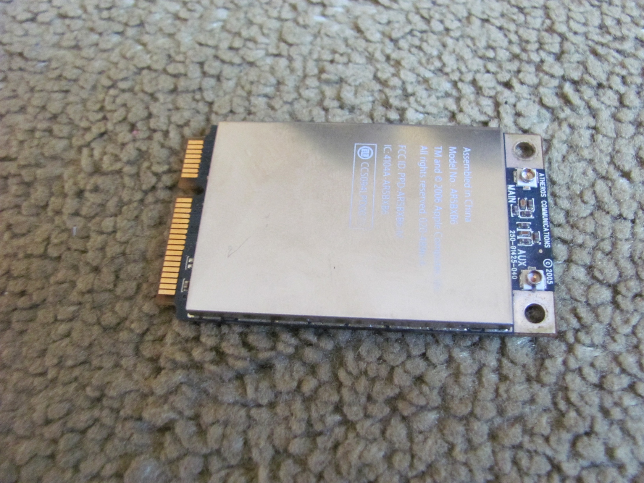
|
AR5BXB72, because I thought it would be a good idea to use an 802.11 A/B/G/N card on the G5 Mod. I also picked up 4 laptop antennas from HP laptops. 3 for wifi, one for bluetooth.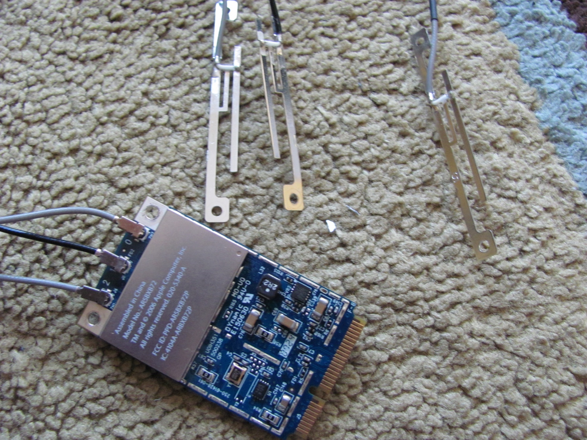
|
The first of my two Bluetooth Modules. Why two you may ask, I will be using the second one as my test module which I plan to over volt to 5v as I don't have access to 3.3v to run it on. If it works, it works. Also, the first one matches the MAC address of the AR5BXB72 because they came from the same C2D Macbook, and the AR5BXB6 and the second one have the same MAC address. Oh and theres also an insulated antenna in the picture.
| |
Heres the second one with the original antenna.
|
Heres a closeup of the second one.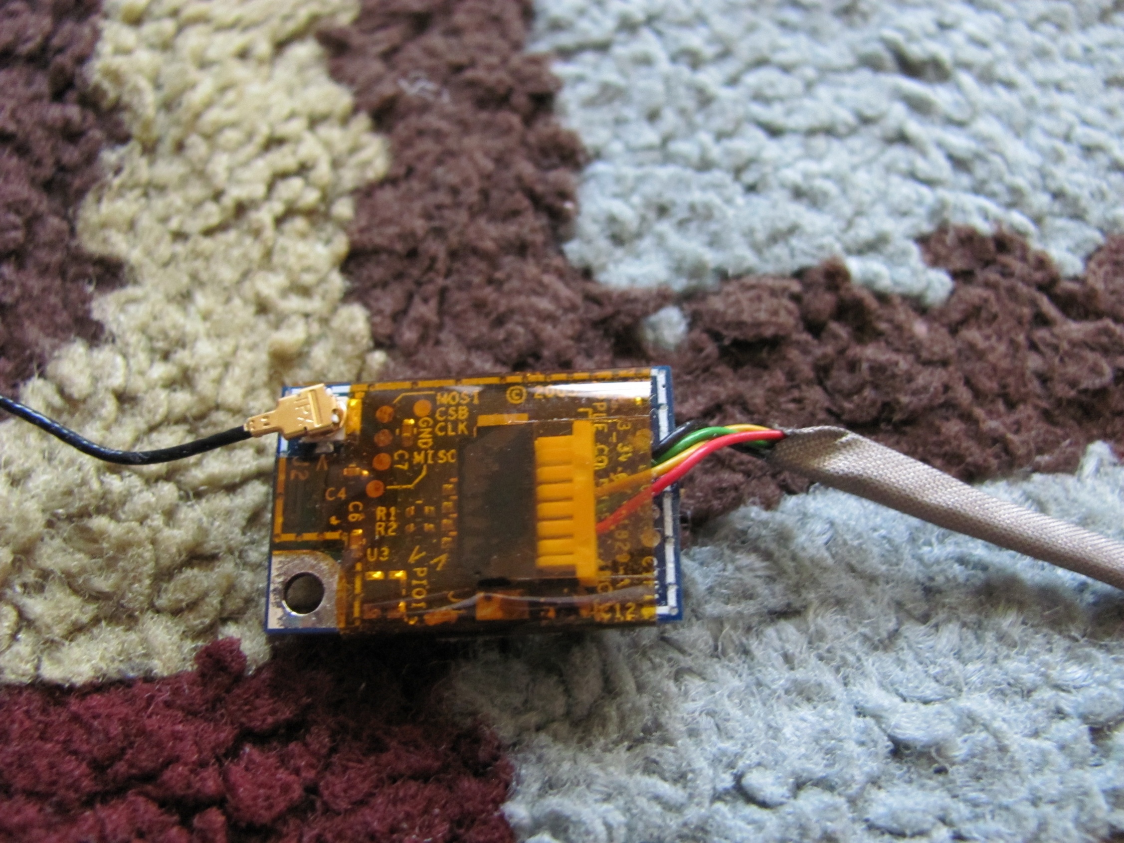
|
Here's the Antennas that I'm using for both bluetooth and wifi. I decided to insulate them in tape like they are insulated in the plastic housing of laptops. If anyone has any idea of how to use the case as an antenna without causing interference with the other three antennas, I would appreciate it if he/she informed me.
|
|
Here's an EMI shield to prevent write errors with the Optical Drive, and also because my case didn't come with one.
|
Here's the IR module from the (Late 2006 I think) C2D Macbook that I pulled the AR5BXB6 form. Unfortunately it is attached to the HDD connector with a 4 pin (hopefully USB) ribbon cable which then in turn connects to the motherboard. I'll have to find which wires in the HDD connector correspond to the IR module. (More info on this later[If I get i to work])
|
Here's one of the optical drives that I might end up using (the other being a standard SATA or PATA one in the top of the case) just for kicks. I extracted this out of the same C2D Macbook as the AR5BXB72 A/B/G/N card.
|
|
Here's a picture of the connector. It just happens to be a standard mini PATA connection like most pre 2007 laptop optical drives.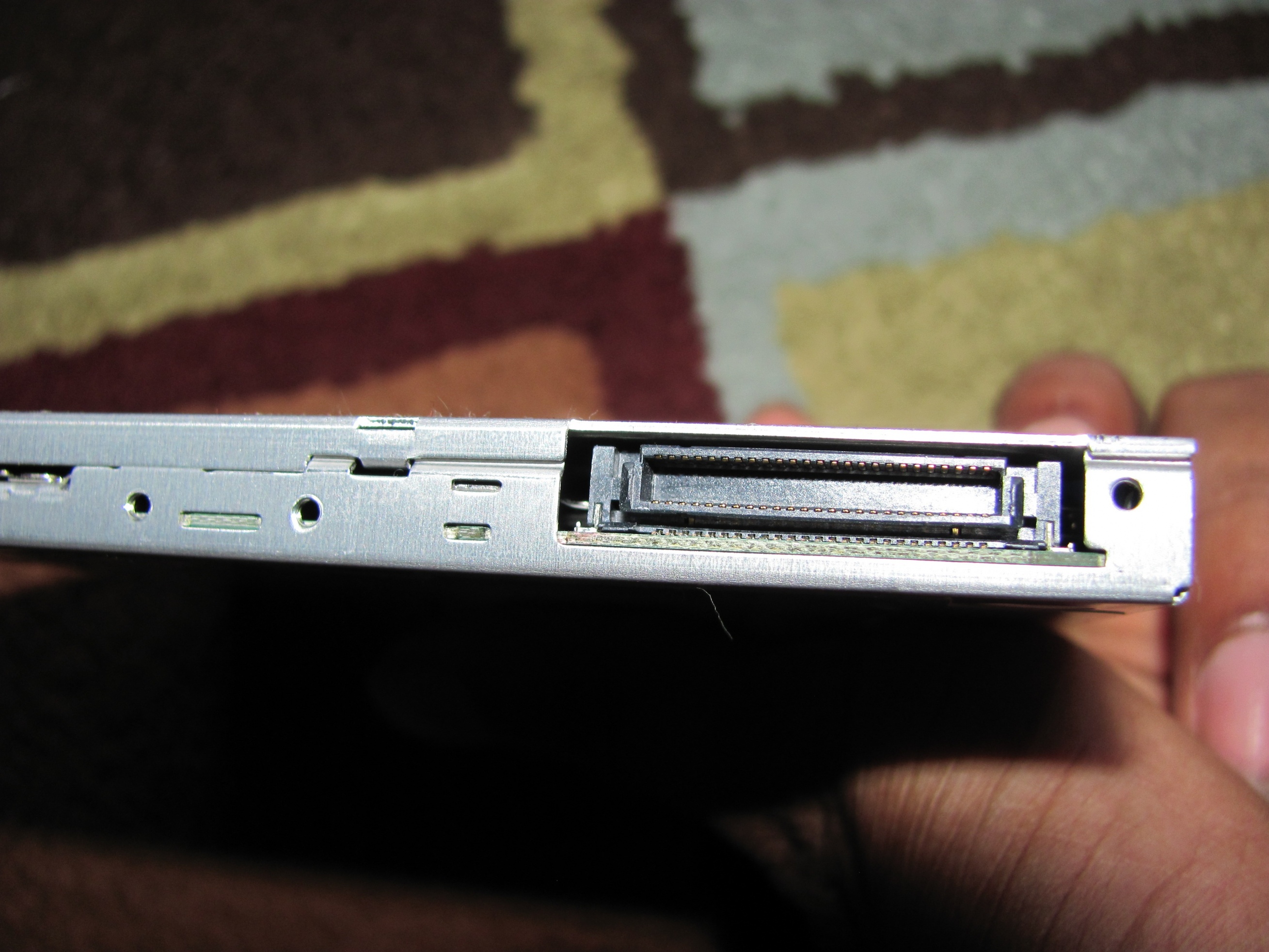
|
... and the supporting wiring that goes with it (I found it in a slim form factor case that was being scrapped).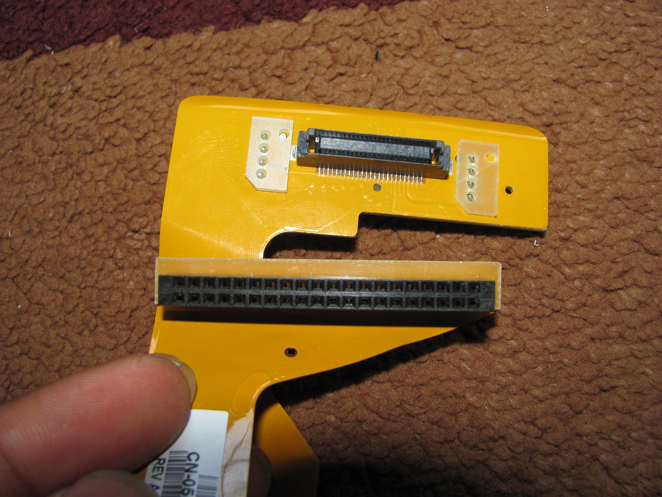
|
Here's just a standard PATA cable that has some nice, flexible wiring that I might use on the front panel cable that I'm making.
|
|
This is just for fun BTW. It's just a CF to PATA connector. I thought it as interesting that CF Cards have the same output as PATA drives as for the supporting circuitry. They're pretty much the first SSDs.
|
Here's the temporary power switch and lights that I'll be using.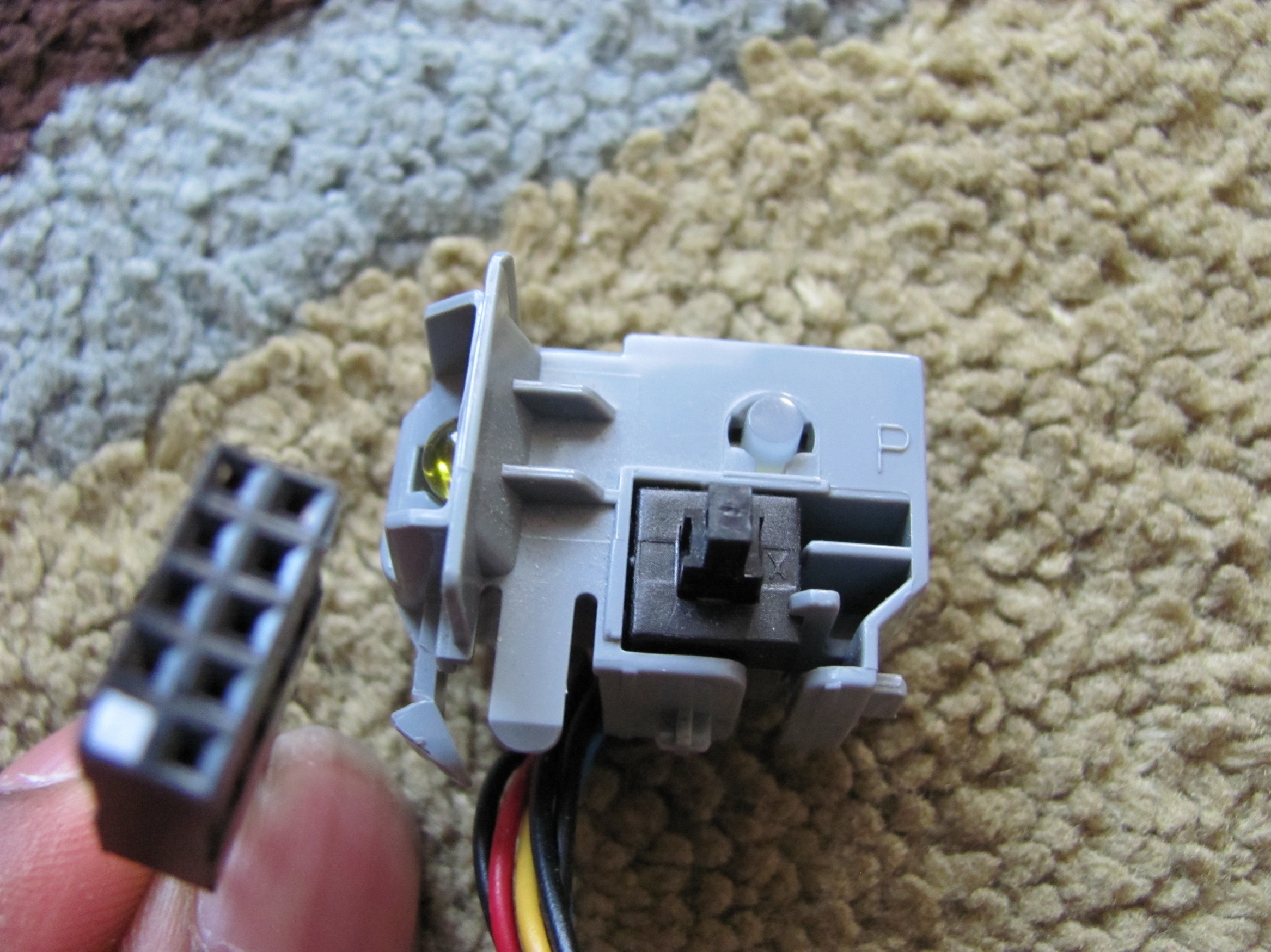
|
Here's a USB card reader that I've decided to use as an internal device.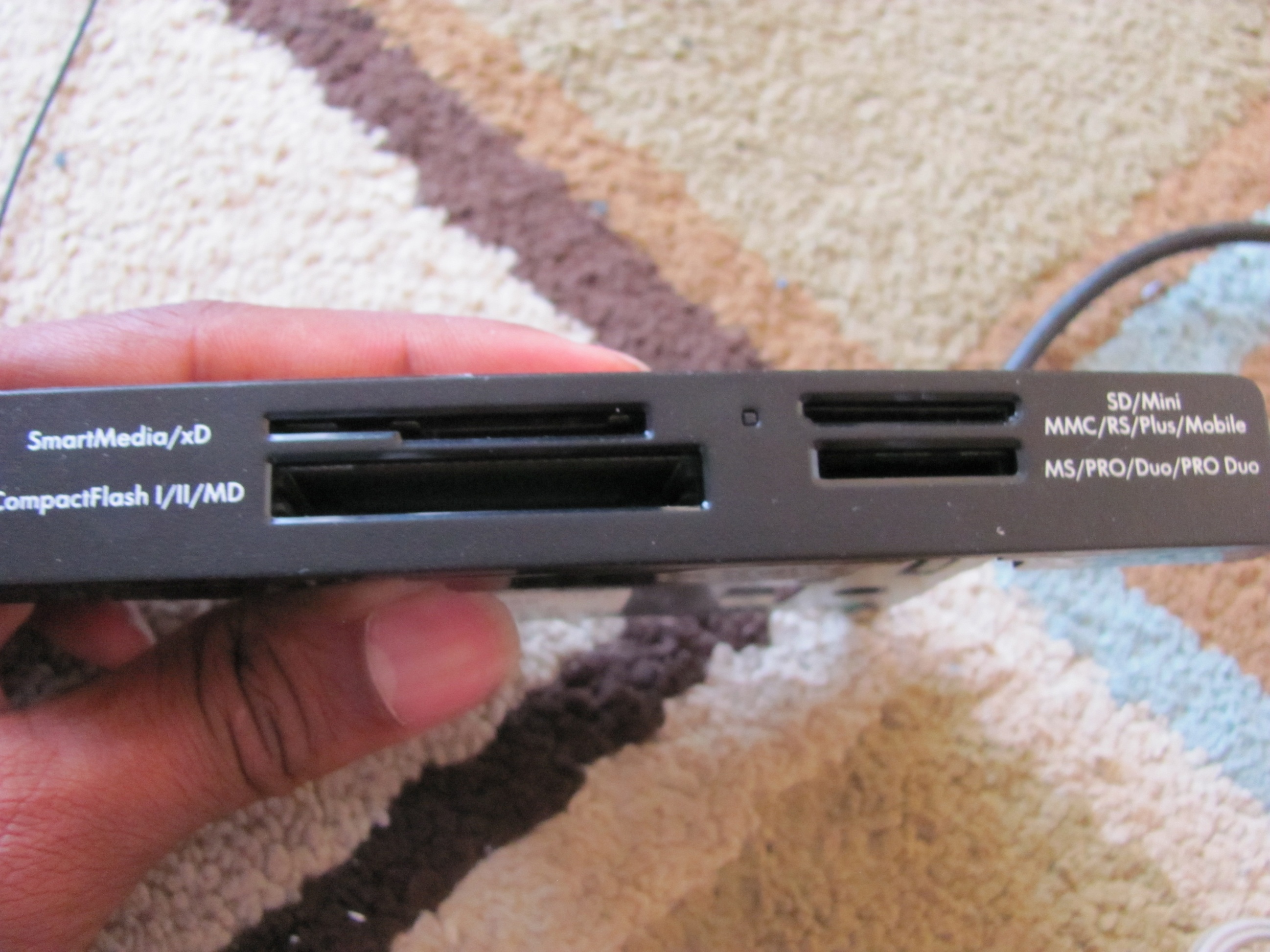
|
|
Here's an adaptec PCI card that has 4 usb and 3 firewire on it. one of each is internal. I plan on using the firewire on the inside as a kind of "header" for the firewire if the motherboard I upgrade to doesn't have one.
|
The first of my two Bluetooth Modules. Why two you may ask, I will be using the second one as my test module which I plan to over volt to 5v as I don't have access to 3.3v to run it on. If it works, it works. Also, the first one matches the MAC address of the AR5BXB72 because they came from the same C2D Macbook, and the AR5BXB6 and the second one have the same MAC address. Oh and theres also an insulated antenna in the picture.
|
Work
So far, I’ve bundled 3 wifi antennas to the wifi card and insulated them all.

|

| \

|
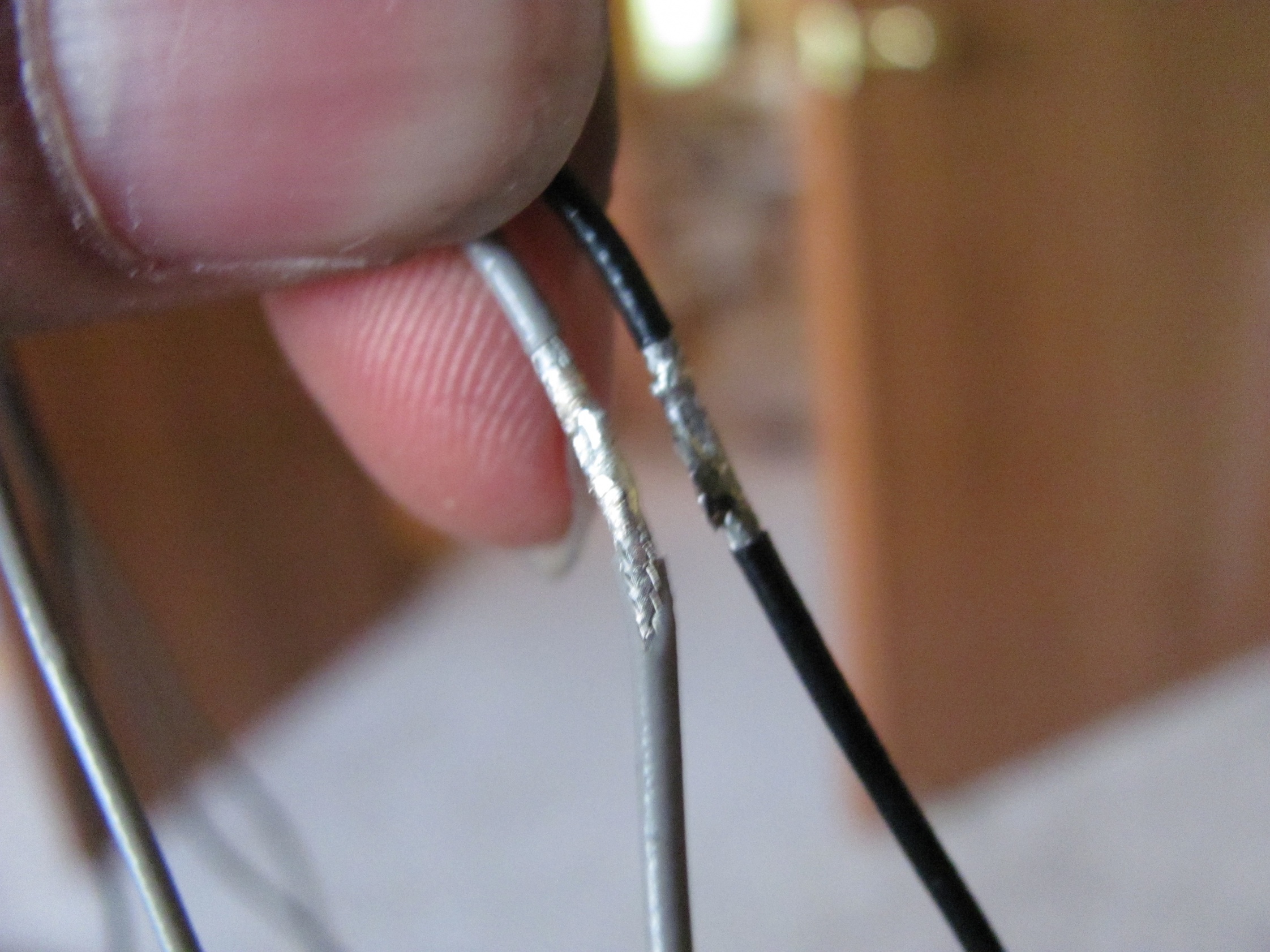
Desoldered the unfortunate solder joint that HP put in between one of the sets of antennas that I got.
And last and not least, made a temporary connection from the Bluetooth module to USB. I know it needs 3.3v and I’m giving it 5v. Anyone have and idea how to see if it’s working on Mac OS X? My MBPr already has bluetooth so that’s the only bluetooth related device hat shows up. Do I have to restart or something of those likes?
Anyway, back to the module...
I cut the connector wire, and I found that the two nonstandard colors in one of the cables was green and yellow, while the other had a light green and pale yellow. as far as the wiring diagram goes, the green connects to the yellow and the white connects to the green. The module itself has nothing to be changed. I stripped the four wires and connected them the right way to the USB cable that I had lying around and... nothing.
Wiring Diagram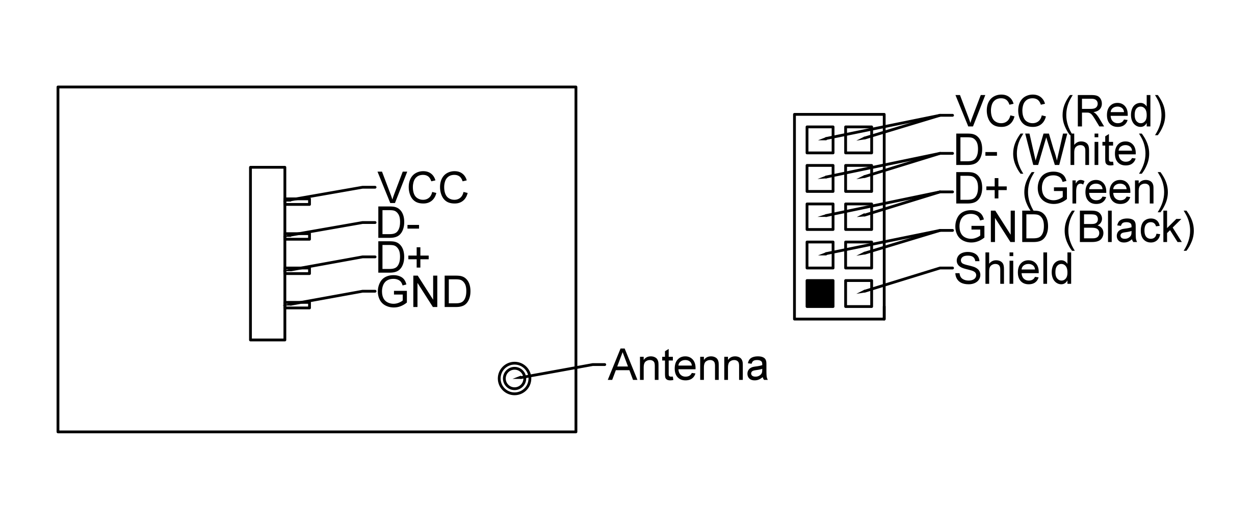
|
I can't get it to friggin work with my MBPr! I even tried switching the two data wires.
August 12, 2013
I was doing some research and ran across this. I's quite interesting and I might end up just replacing the stators for the two 92mm fans in the back.
Disclaimer: The following sketches of back panel parts are not exact and may be off by +- .5"
I sketched the two parts that make up my backplate, and finalized them with Minihack. Unfortunately he wouldn't be able to get them cut out until at least September 14th. My design has two parts, the hook and the blade, just kidding. Anyway, it has two components to it and they fit together in a steplike design. the top plate will be flush to the outside of the case while the bottom part secures the top part to the case. The two plates will be glued together and the bottom plate will be screwed into the case with (hopefully) the same screws as the ones used to fit the fan shroud.
Top Backplate 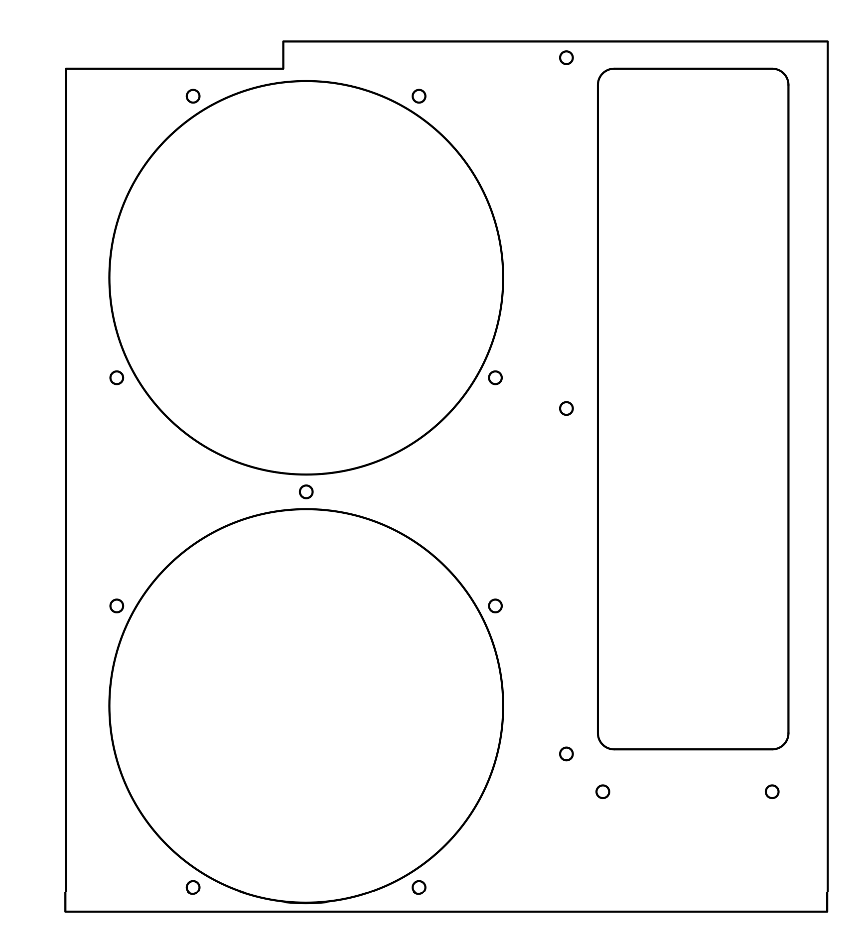
|
Bottom Backplate 
|
August 14, 2013
Today, considering the fact that if I used the original G5 PCI bracket, there would be a 3/4" gap between the IO Shield and the IO ports, I've decided to just order an ATX conversion kit from The Laser Hive, or fabricate one myself out of old cases, and laser cut Aluminum. I'm still going to try to make the backplate flush, and I will still use the dual 92mm shroud that is standard on the G5.
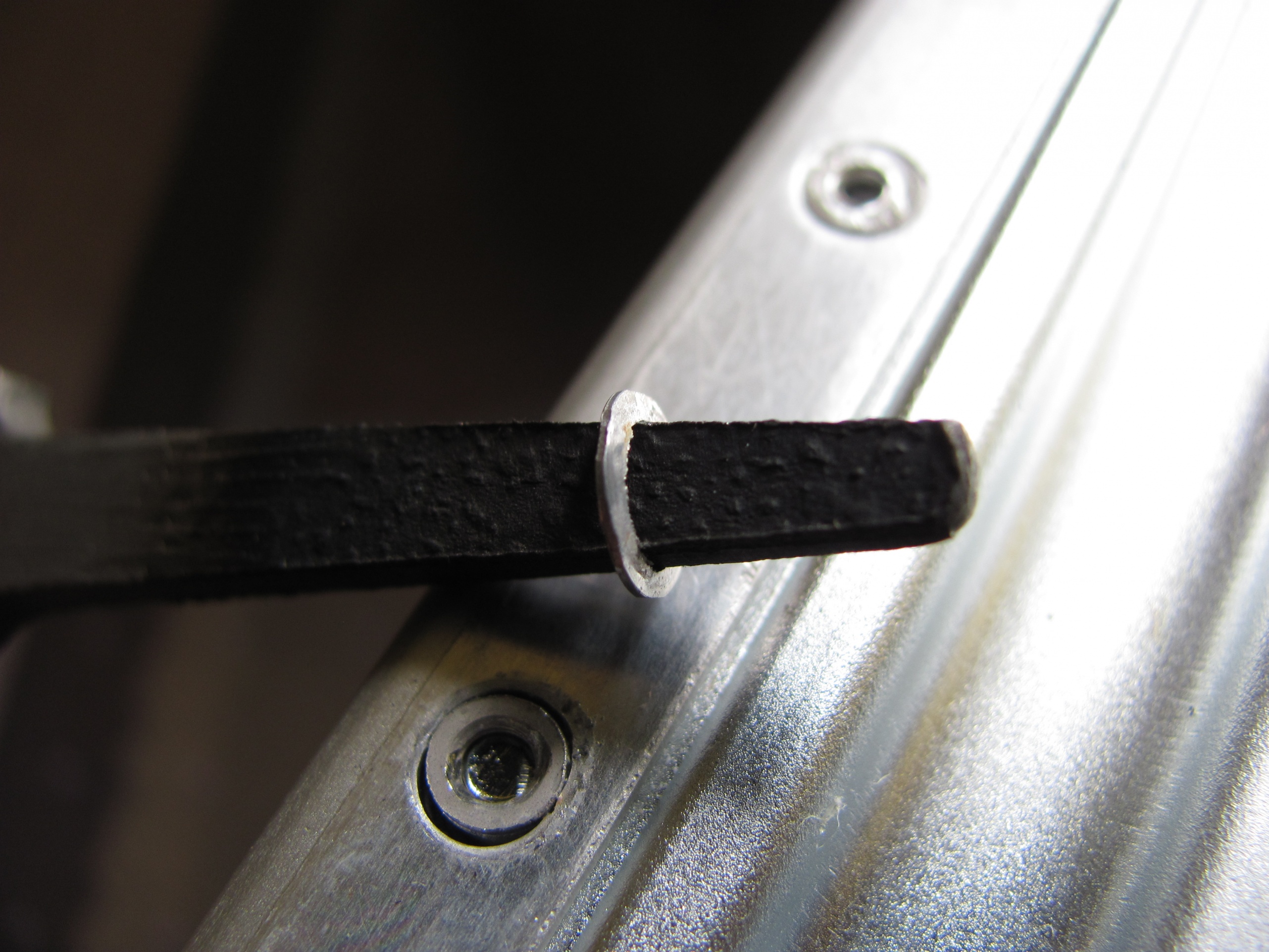
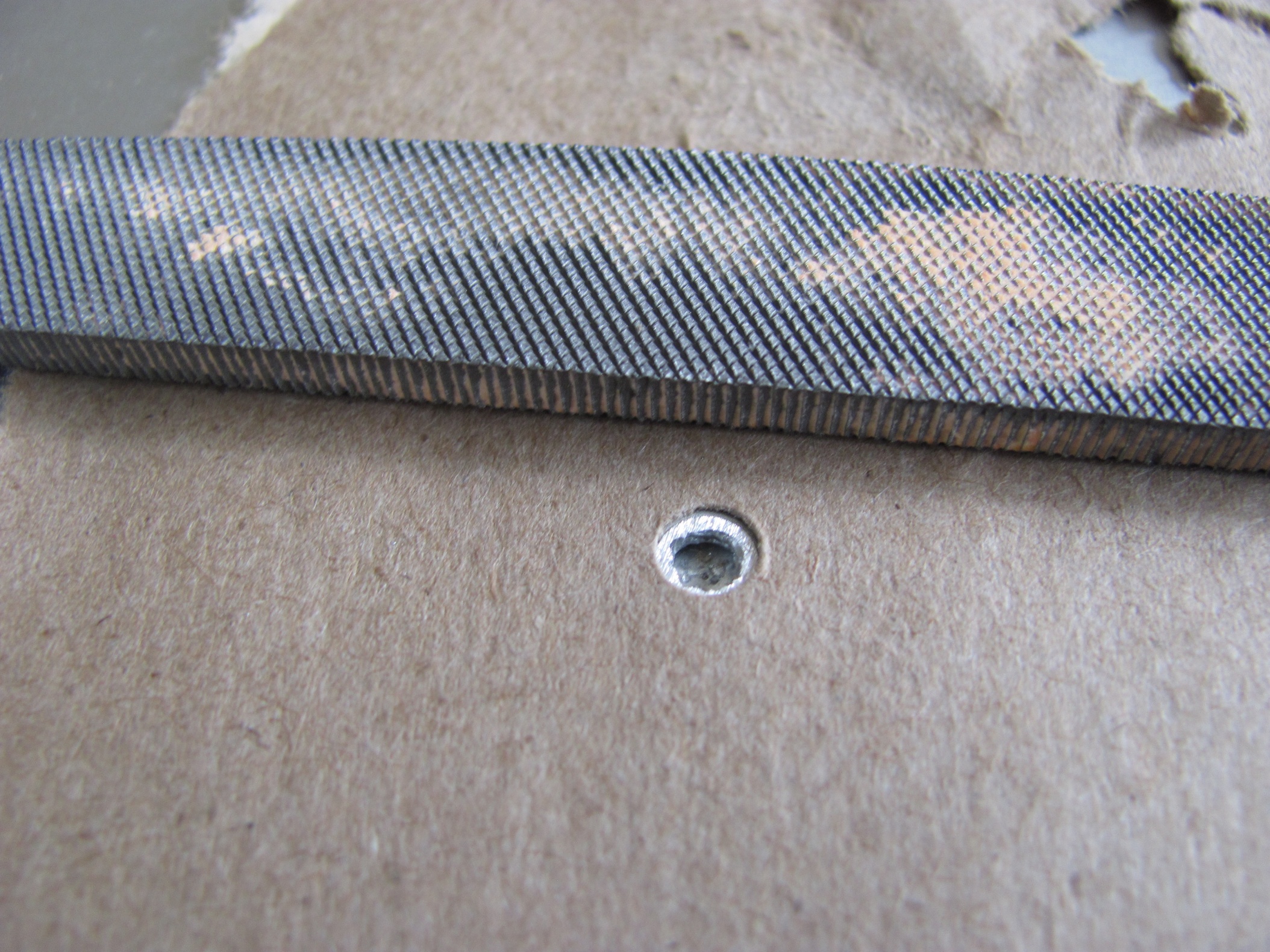
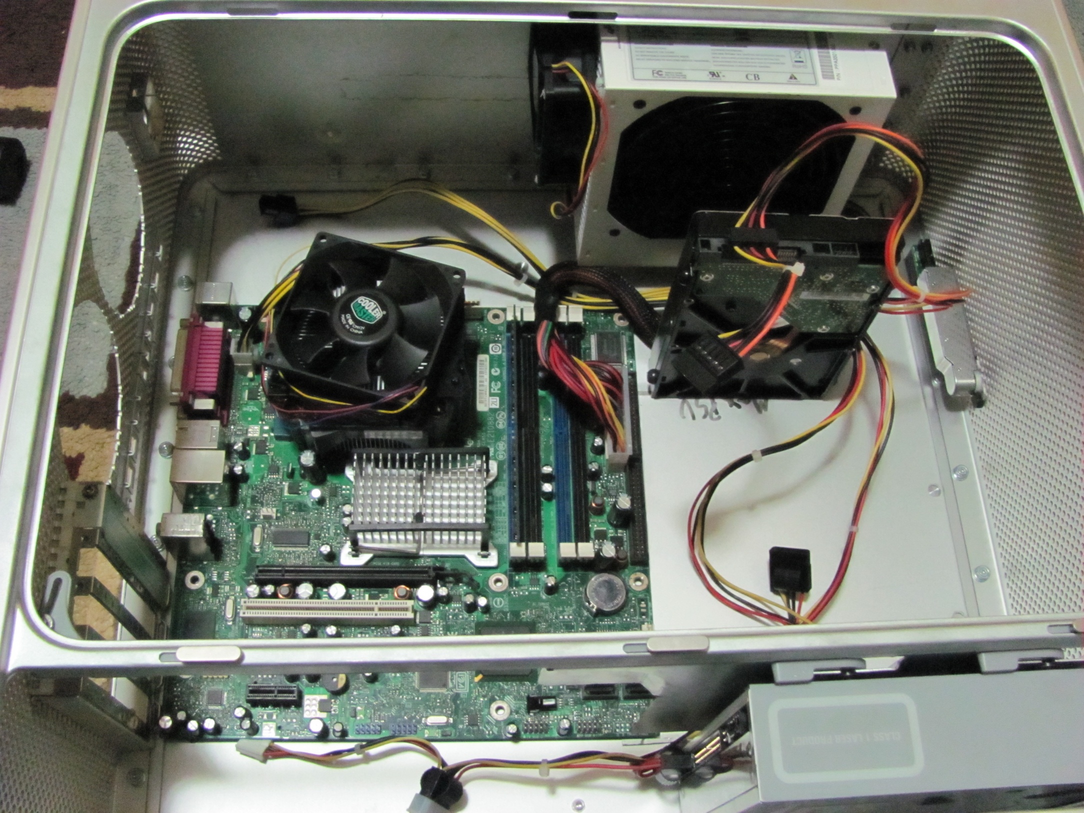
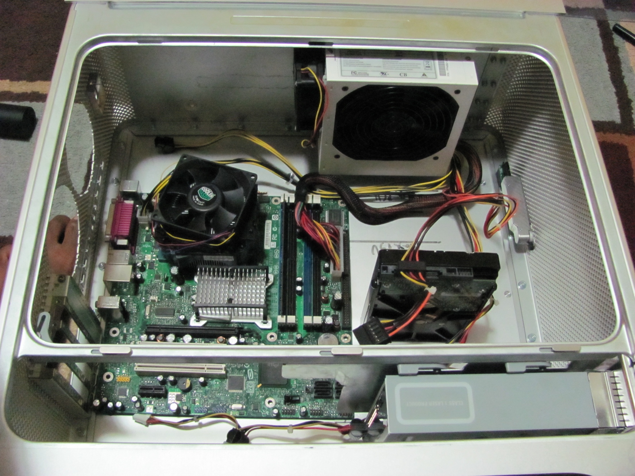
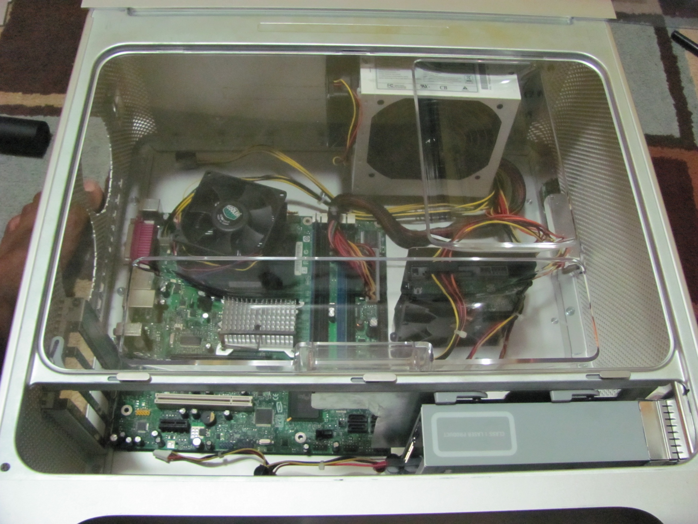
I also took apart the case today. I found this guide for people confused about how to do this.I had to take out circa 100 screws and nuts, then I realized that the two parts of the inner G5 are riveted together, and put the nuts back to hold that in place. I also couldn't get one screw from the bottom door side of the case, and ended up stripping it. Luckily the mount (threaded female part) was fused into the case just like the motherboard mounts, and after ~30 minutes of struggling with it, I just popped it off. I then took the sharp part of my file and punched the screw out of it's hole. I'm happy to say, there was no damage in to the case except taking a bit of aluminum off the inside of the case (I don't really mind) and the stripped screw (of course).
|

|

|
|
I also sanded down the little mount that I tried to pry off and failed at. the best way, I found was to take a piece of paper, put it on top of the part you want to file and start filing. The file will cut through the paper and file only the part and not scratch any of the other parts of the case.
|
Aug 22, 2013
Sorry I haven't updated in more than a week, but I was busy with other things.
First of all, I placed the 3 wifi antennae in the case on the top part of the solid aluminum.

|
|
|
|
Turns out, the signal is really weak, and I couldn't see my own wireless network, but I ended up picking up my neighbors. So, after that blunder, I decided to get rid of the current arrangement, and decided that I would get that sorted out after I get an acceptable mPCIe to PCIe x1 converter (I'm looking for a cheap one without antennas).
About the 19th, I borrowed a Dremel 300 from my First Robotics team.
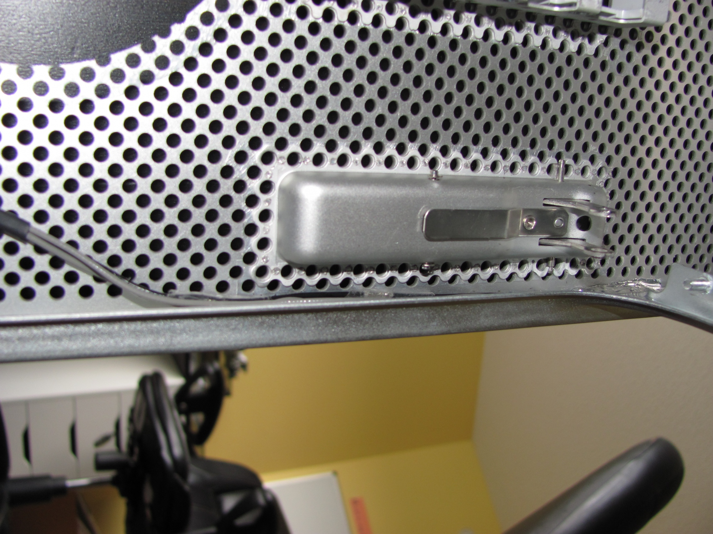
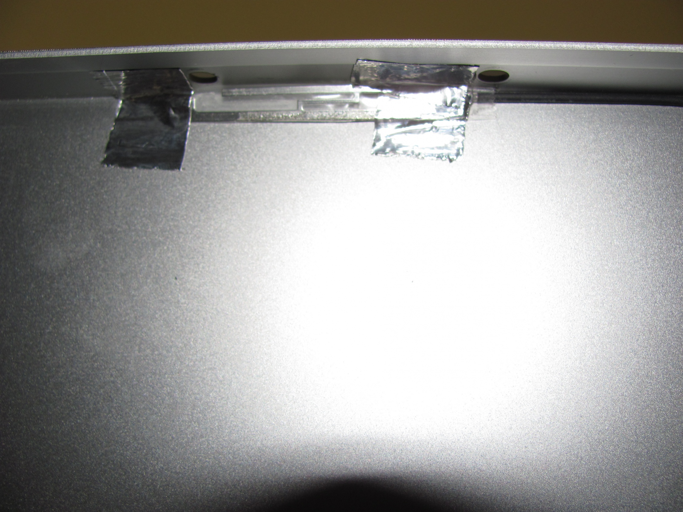
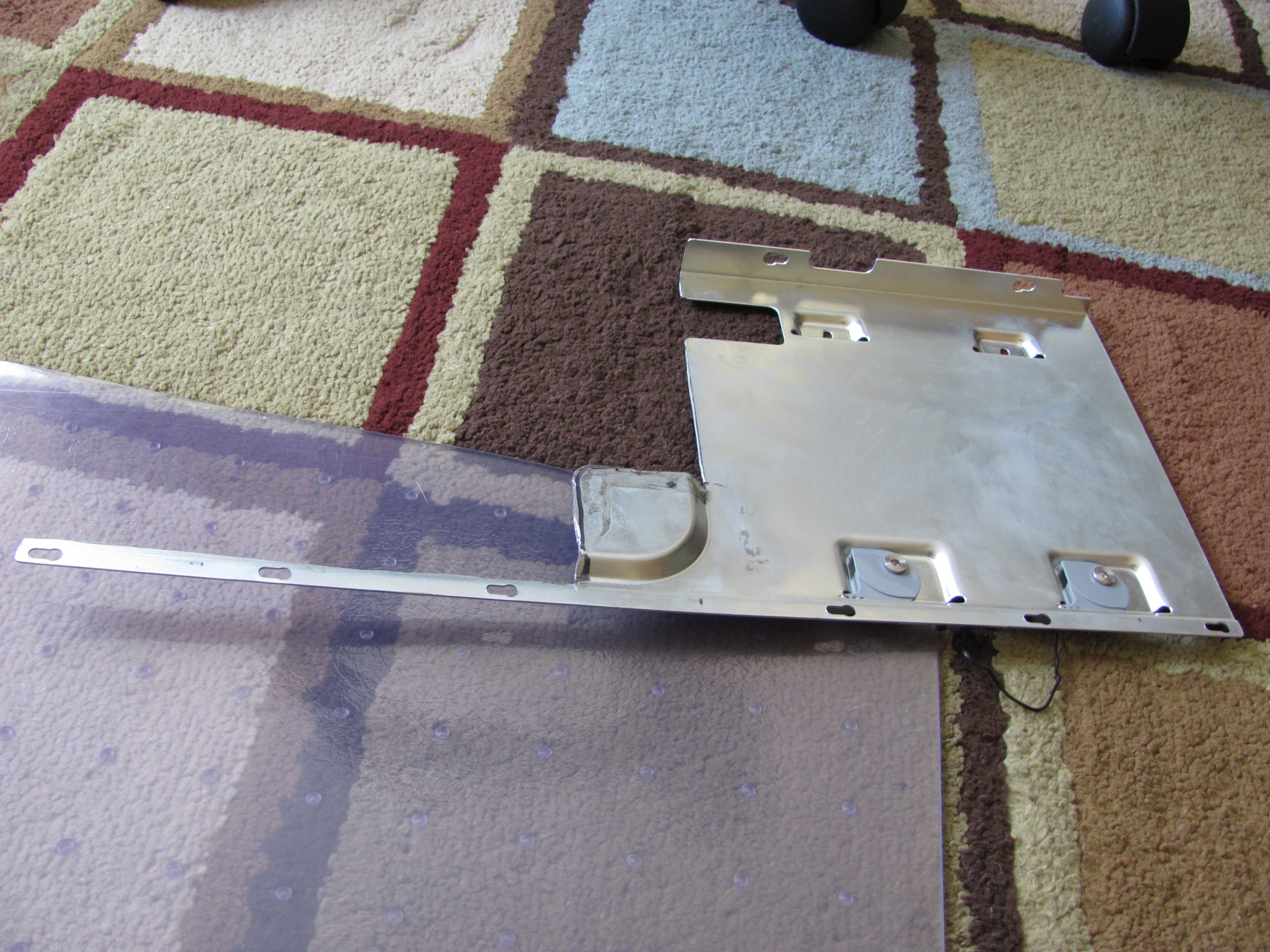
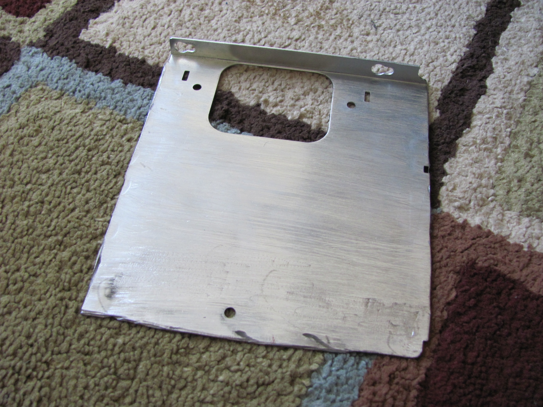
Next, I cut the DVD plate to the correct dimensions. the little strip is because the locking mechanism and the metal bar it attaches to have a slight gap in the middle that keeps the latch from clicking shut.
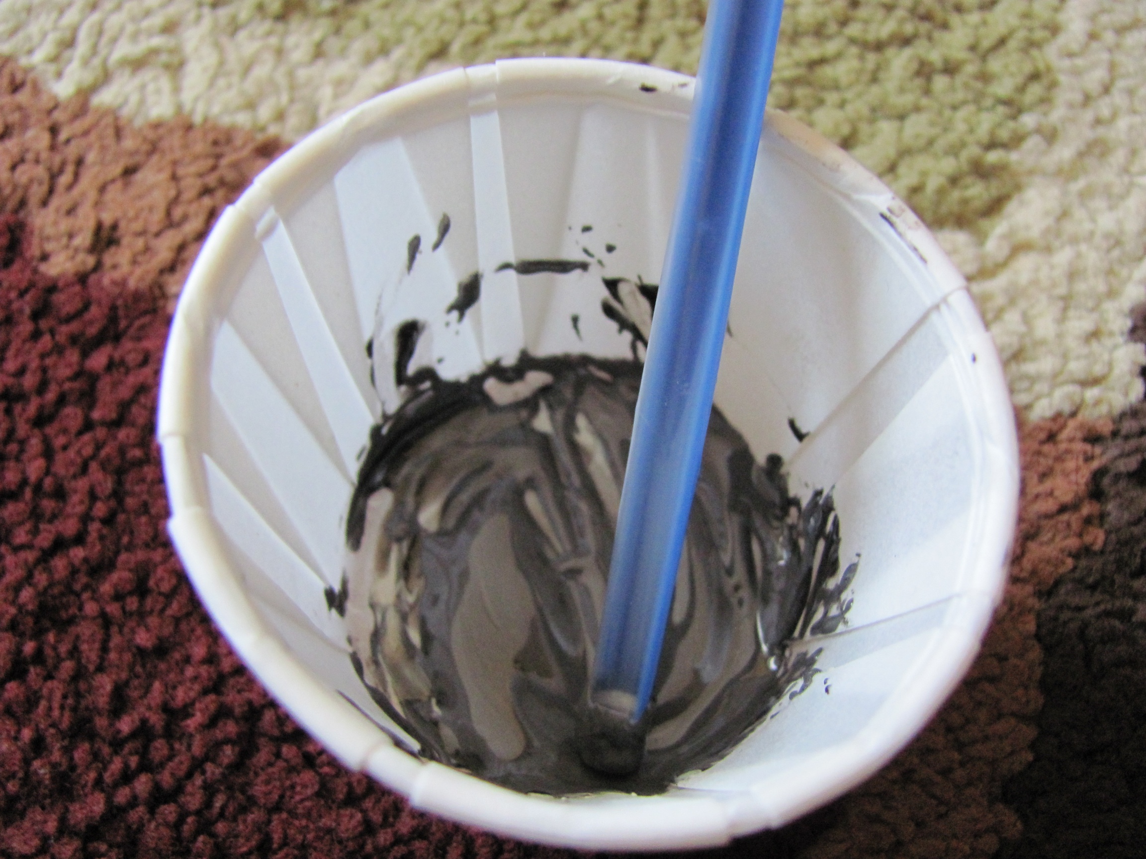
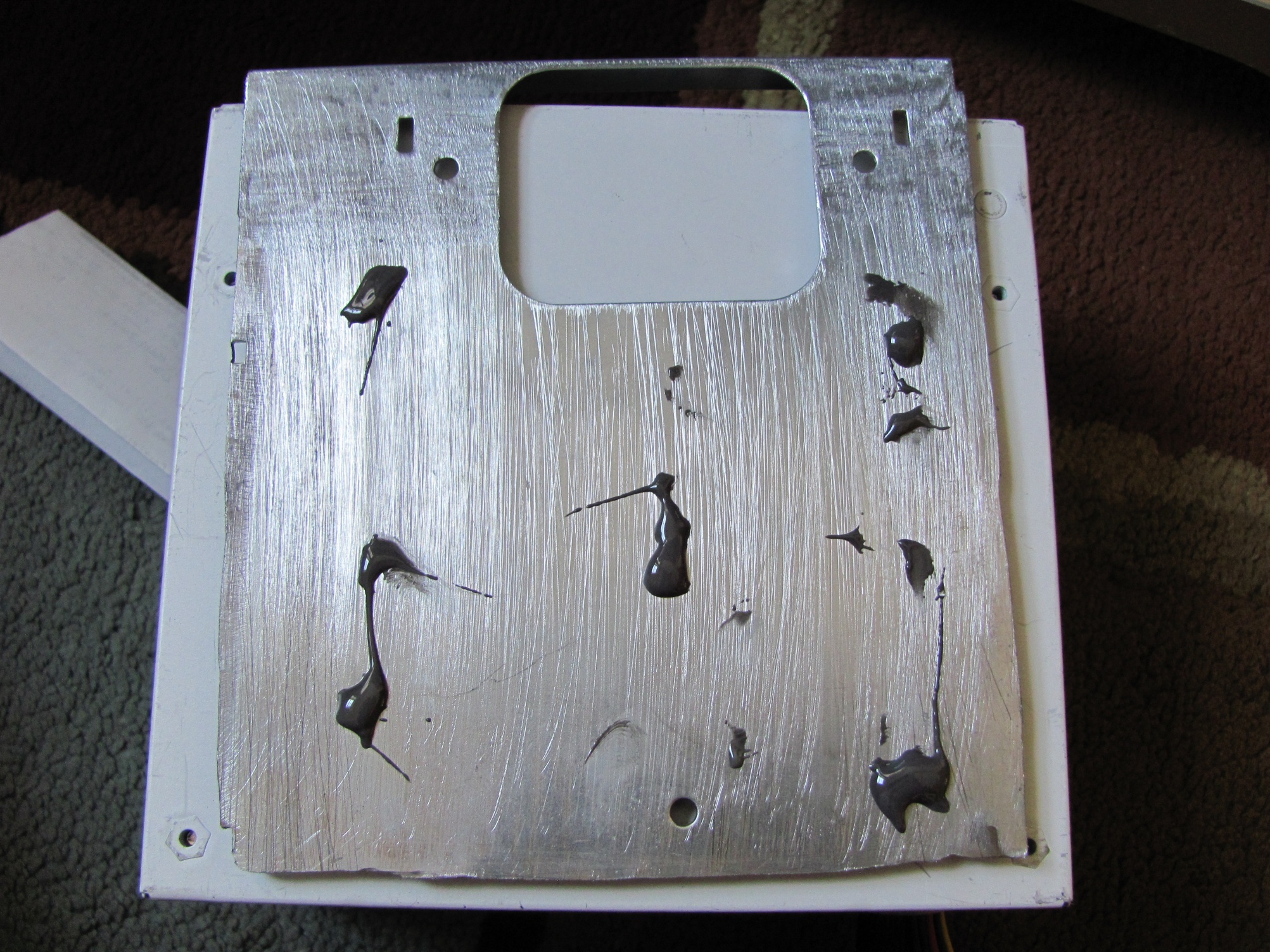
I almost threw out the rest of the metal plate, but a family member (Thanks Mom!) decided to save it just in case I needed it. Turns out I did need it. I originally decided to cut the excess off and bend the rest and have the PSU screw in, but then I released that the screws would be inaccessible, and so revised my design by cutting a little more off. Then I thought about using magnets to mount the PSU, and the third design I came up with has the ability for PSU position customization. I attached the magnets to the plate, and the plate to the case using JB Weld. I totally forgot that JB Weld has steel filings until I pit it on a magnet, and it started spreading by itself. Oops...
|
|
|
|

|
|

|
I originally had 3 easy attach cutting wheels for metal, but after the cutting and re-revising of the PSU plate, I ran out of them.
I decided not to use the original G5 front panel cable because I thought it was disorganized. Instead, I opted for a (mini) IDE style cable that I found (currently used for the serial and parallel headers on newer motherboards). I liked this because the number of the cables went up in ascending order instead of being intertwined and being split from the origin. I tested to see which done was pin 1, and after I found it, I aligned it to the G5 pin 1. I will wire this up to standard Firewire, USB, and Audio headers as well as power button and light.

|

|

|
Here's the final plan for placement. The single HDD signifies the rack since I don't have one.

|
|

|
|
|
|
|
August 23, 2013
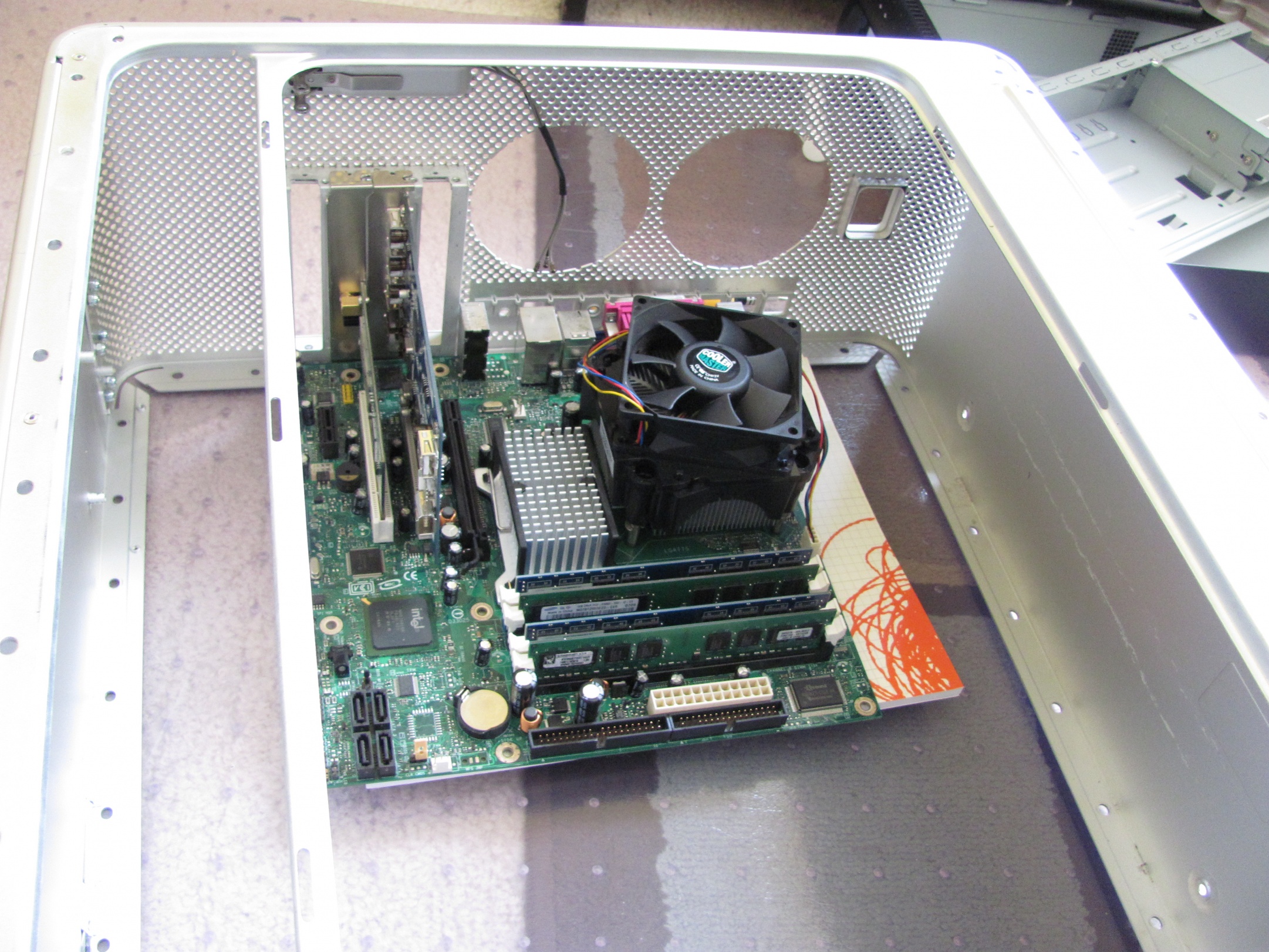
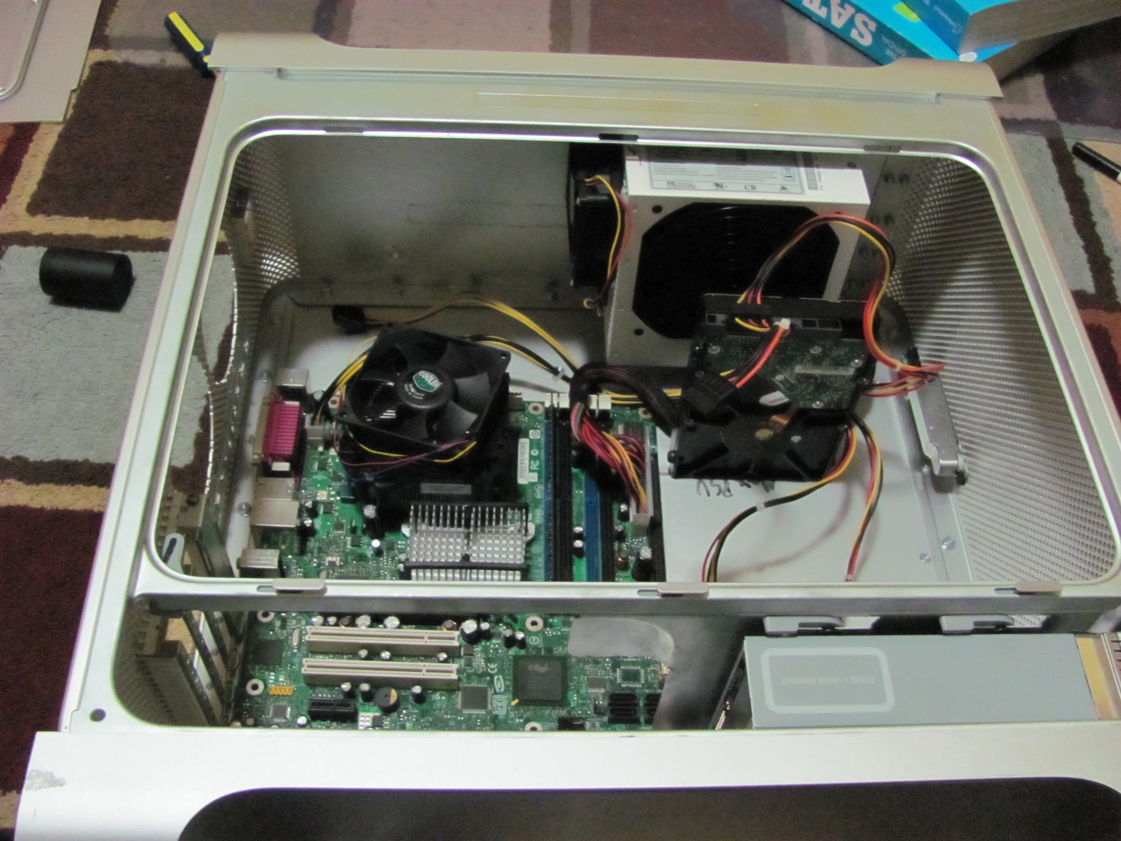
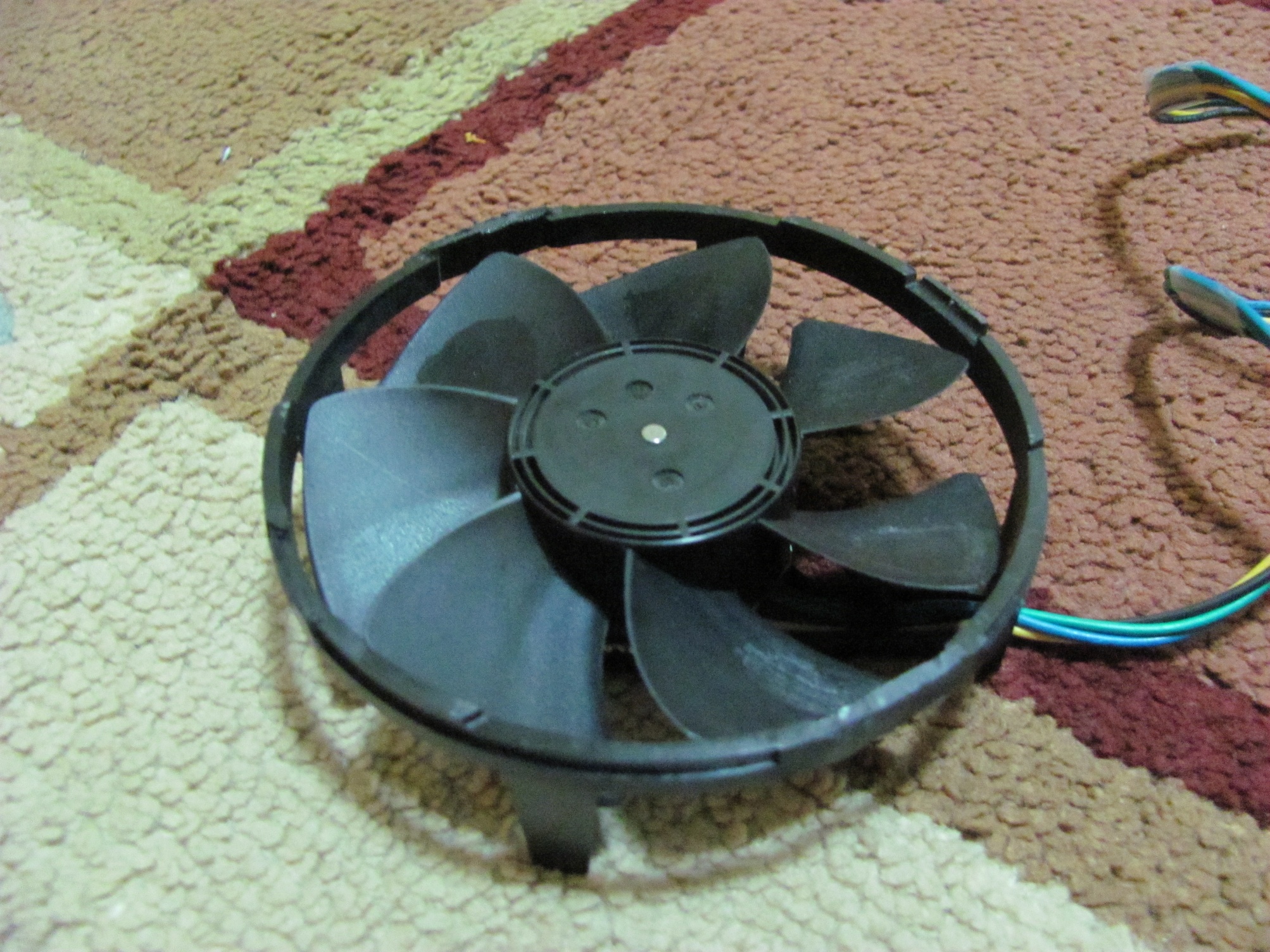
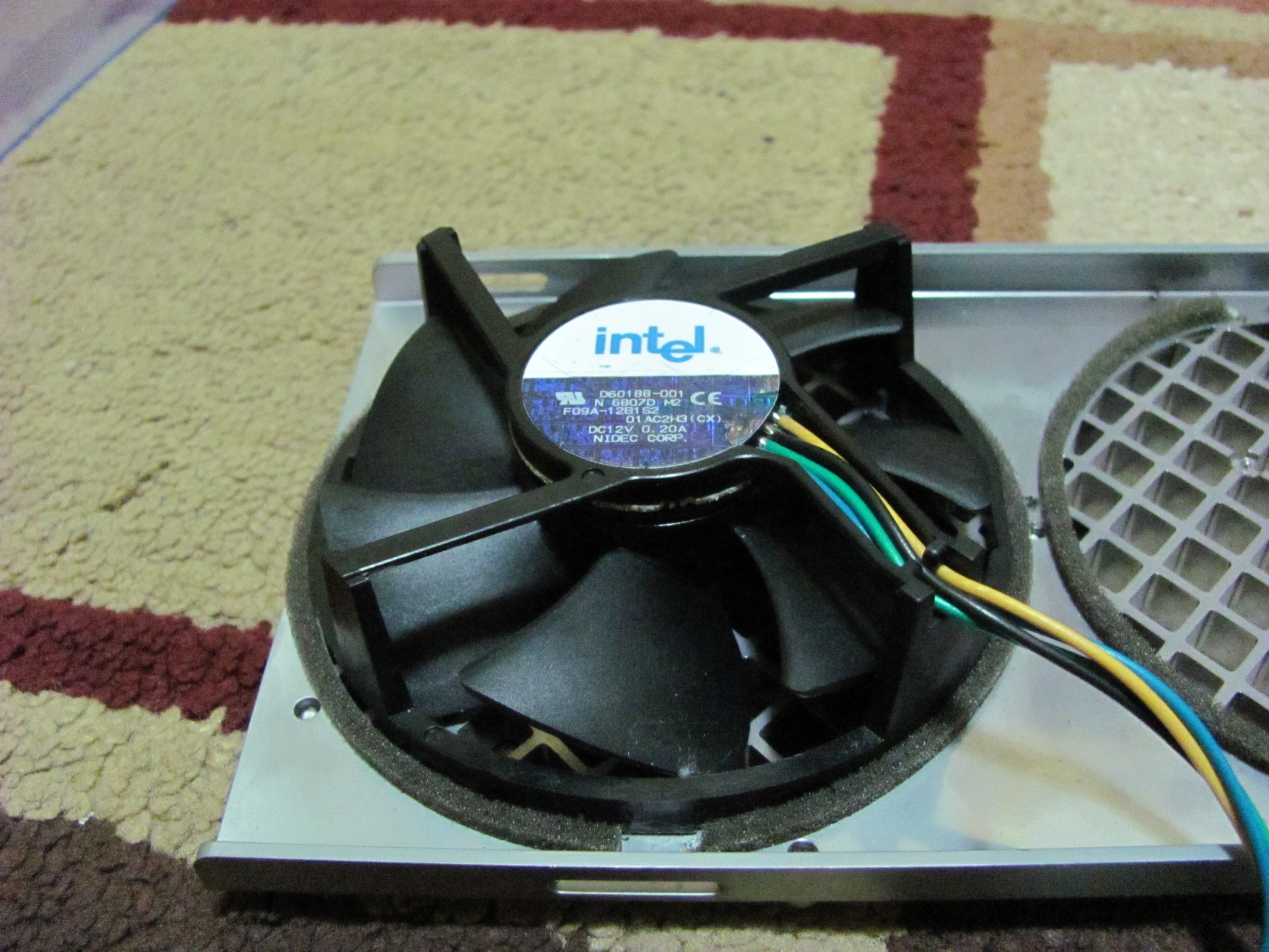
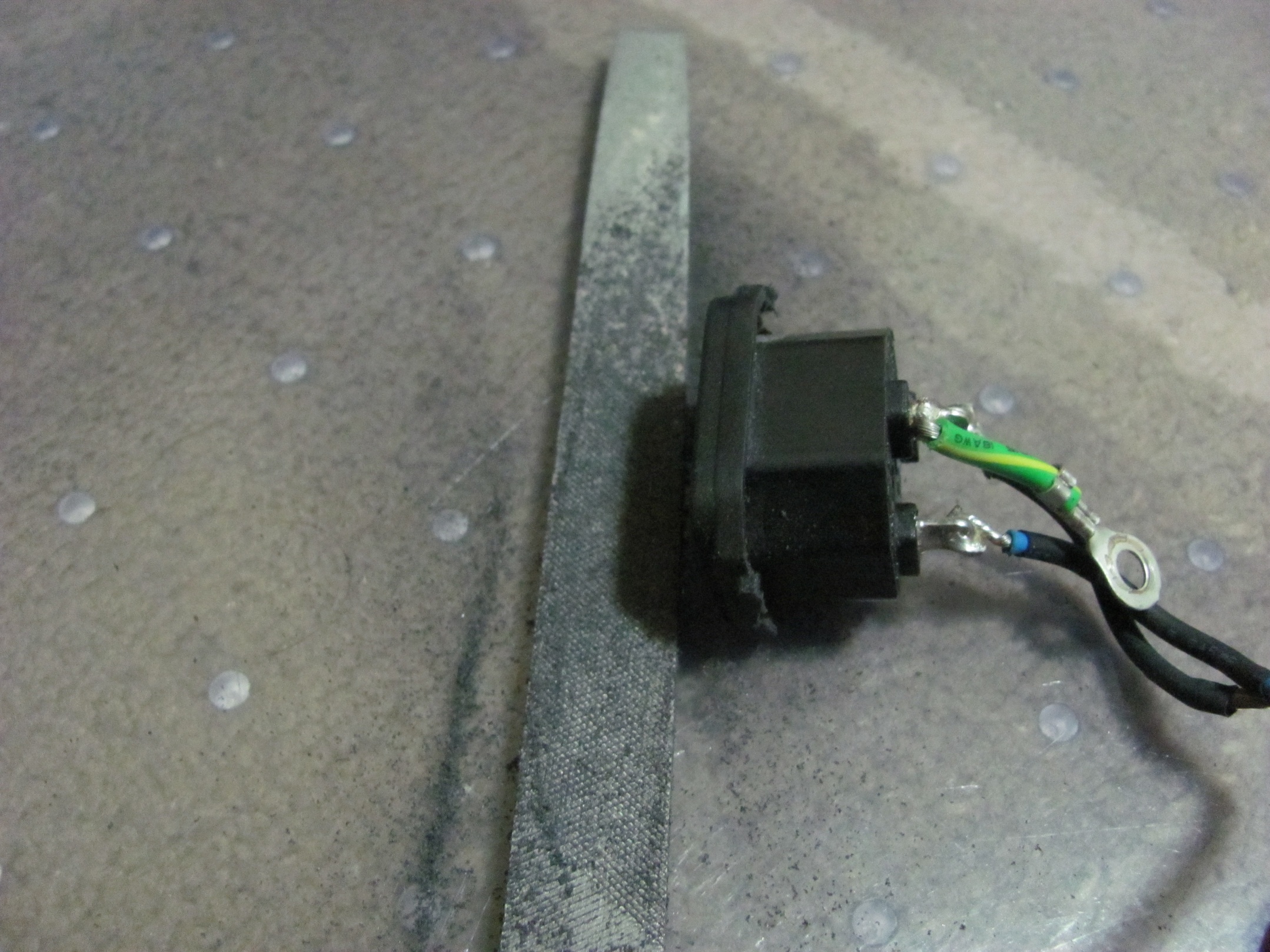
Today's progress was minimal. I figured out that a stock LGA775 Intel fan could fit instead of a 92mm fan into the fan grill, and also had a spark about using a screw-in power plug in a pop-in socket.
I first dremeled (yes, I got more metal cutting wheels for the dremel) off the standoffs that existed to attach the fan to the stock heatsink, and filed it to be flush (Sorry, I forgot to take "before" pictures). I will later attach the fan to the stock apple fan grill tomorrow as I don't feel like firing up the hot glue gun.
|
|
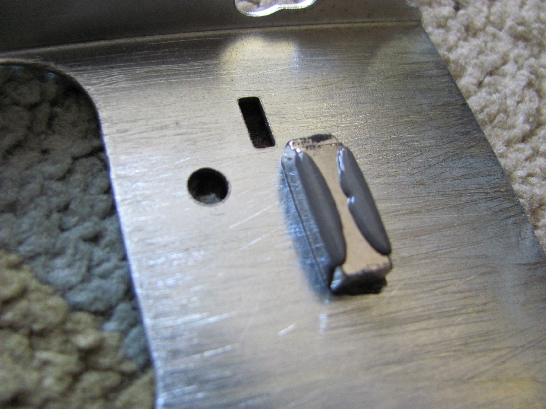
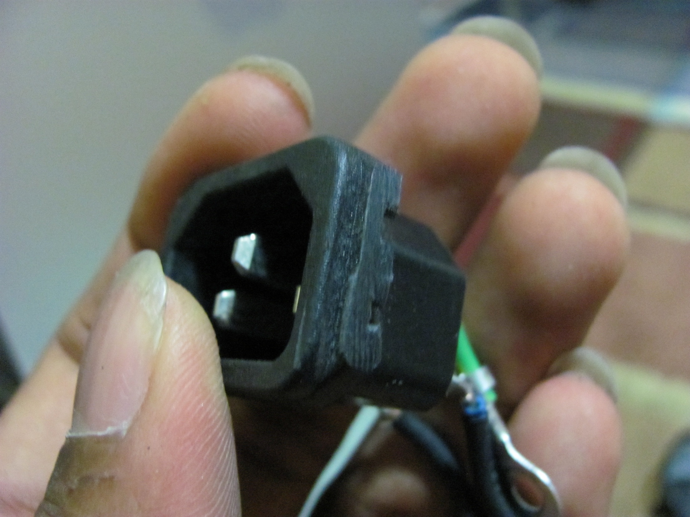
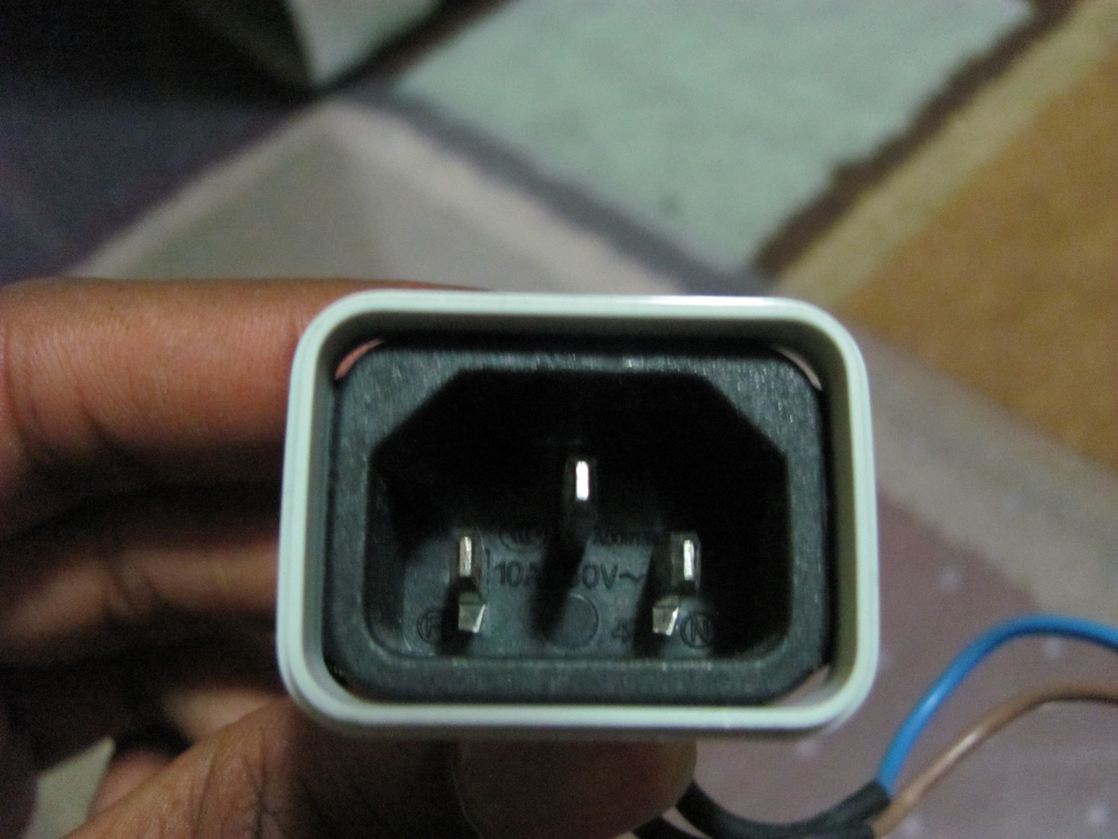
I then cut off the two pieces that enables the power plug to screw in, and then filed it until it had a snug fit in the G5 socket (Sorry, I forgot to take "before" pictures). I will also hot glue this tomorrow as it's late and I'm lazy. I also need to do the wiring tomorrow.
|
|
|

|
The plans for tomorrow are to get another LGA775 fan and a HDD rack that will fit in my case. I also need to get some perspex for the front fans that I'll be putting in later, as well as an incorporated case speaker that (hopefully) does the chime.
August 25, 2013
Minor Update: apparently I finished
I only have one picture of the final build apparently, and i put it on facebook so its gonna be really compressed.
Attachments

Last edited by a moderator: