Contribute
Register

Template for early G4 (poss G3) motherboards

Status
Not open for further replies.
Joined
May 27, 2010
Messages
2,364
Motherboard
Dell Optiplex 9030 All in One
CPU
i5-4690K
Graphics
HD 4600
Mac
  1. Mac mini
Classic Mac
  1. iMac
Mobile Phone
  1. iOS
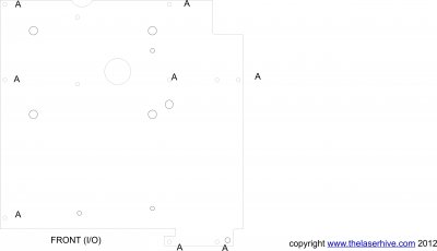
AGPG4Motherboardnew.jpgAttached is a pdf that if printed out full size and the holes cut where marked will lay over the standoffs, holes and posts on an early G4 "door" and show the correct mounting place for ATX type standoffs. This will align your ATX first PCI-e card to go to the first slot on the G4 door.

This is the template that I am using when I make up my perspex motherboard tray for these models but if you just make it from card it will allow you to mark the exact positions for your mATX board without even having to dismantle all the door.

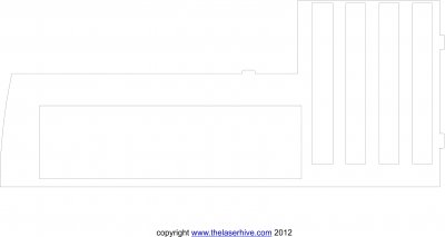
I am fine tuning a blanking plate for the front I/O portion (to make sure the I/O opening is at exactly the right height) that will help also people to make cuts in the right place - or if they use it as a blanking plate can cover up any bad cuts they might make.....

These I hope will help people to make their own G4 conversions - and encourage user jmpa NOT to give up!!!

Important note: I am posting this to help out. I believe it is accurate for the models indicated, but cannot be held liable for it please. If something looks NOT right when you print it out then don't use it. Also note that it assumes you want to use all 4 PCI slots and therefore that unless you choose your mobo carefully or cut the pillar (you will know what I mean...) then audio ports may be obstructed. Any questions on the template you can post on the thread or PM me.

AGPG4Motherboardnew.pdf
 

Attachments

  • AGPG4Motherboardnew.jpg
    AGPG4Motherboardnew.jpg
    326.9 KB · Views: 12,564
  • AGPG4Motherboardnew.pdf
    12.2 KB · Views: 867
AGP inner Shieldnewcdr.jpg
As with the other template this should help G4 modders. This is the basic layout on the back shield for early G4s to go with ATX format. If you print full size and cut from cardboard it will help you in your left/right alignment of the I/O cut out. Please note that the height of the slot may not be exact yet as this is my work in progress, but it at least will be a guide to let you do some initial cuts.

This is what I will be fine tuning and making into part of my "kit" to smooth the way for G4 mod.s

NOTE: Me posting these files is intended for your own private use and not for commercial use by you or anyone else. It is a present for users of tonymacx86.com only! Questions on this feel free to PM me.
 

Attachments

  • AGP inner Shieldnewcdr.jpg
    AGP inner Shieldnewcdr.jpg
    160.6 KB · Views: 1,859
Sweet.. definitely come in handy down the line. Would the door latch mechanism be lost using these?

Do they sit right flat against the side door? So there is no space underneath them?
 
anyone to do the same for a G5? :D
 
Hi Gus,

There are two options.

1. Use as template for drilling or JB'ing
If you just print out on card it is simply a way of marking up on the door where to drill or JB your post fittings for ATX. You would of course also need to pull off or dremel the old G4 standoff (but that can be done at the same time as you do your new post fitting). Once you have fixed the posts you can make the "race track" type slots in the plastic latch and keep that in place.

2. Use as a mobo tray tool
Alternatively, if the template is used the way I will use it to make a mobo tray from 5mm perspex then you would need to get rid of the plastic latch and then you can screw the template directly to the empty M3.5 screw holes that are already there on the door and use the "Spackley" reverse spring method to latch the door shut.
Advantages of using it for a custom tray are that: (a) Instead of twisting out the G4 posts (which are a LOT harder to pull than on a G5 and can distort the panel when you remove them) you can just trim them with a dremel to below 5mm height;
(b) No drilling or JB'ing means not making fresh holes in the door (in fact by attaching to empty screw holes you are actually filling them (!)).
(c)The holes in the template for the ATX fittings are 3.8mm in diameter to fit brass threaded M3 inserts that I use on mobo trays and these can be used then with m3 posts, bolts or M3 PCB standoff directly.
(d) Perspex is insulating and so no danger of shorting out....
 
Am also doing a similar layout diagram for the Quicksilver.

Disappointingly though the Quicksilver does not have any "spare" threaded holes in the backplate so if you wanted to use for a mobotray you still need to make some holes. As a guide template though for helping you get your ATX standoffs in the right place it will do the job.

I might re-visit another MDD at some point and do a more standard conversion on that one. When I get around to that I do I'll do a layout for that one too.
 
Hey,

Thanks for this thread. It should help a lot of people for sure.
I have some doubts. Don't understand that thing in red, what is that?


My motherboard is micro atx.
Another big problem I had was the mb needed to be to much high and the standoff were to low, and I bought two sizes (http://computershopper.com/images/tips08/8.jpg)

In your case what are the size of standoff?
 
jmpa said:
Hey,

Thanks for this thread. It should help a lot of people for sure.
I have some doubts. Don't understand that thing in red, what is that?


My motherboard is micro atx.
Another big problem I had was the mb needed to be to much high and the standoff were to low, and I bought two sizes (http://computershopper.com/images/tips08/8.jpg)

In your case what are the size of standoff?

The thing in red is so the tray can fit around some of the extra metal that is in the G4 case without having to cut them. So the two holes near the "A"s are for standoffs and the hole on the right is where there is a rivet on the G4 door (so that the tray fits around it).

When the motherboard tray is 5mm thick (and flat against the metal door), then spacers of 4 to 5mm on top of that tray will get the PCI cards fitting okay except for the two closest to the I/O plate which need to be slightly shorter because the metal around the door plate rises a little bit where the I/O joins the door - so instead of using standoffs I use posts and spacers.......spacers of 2 to 3mm (washer) for the two nearest to the I/O and spacers of 4-5mm for the rest.

I will put a picture and instructions up when I have time to finish the design, which will be next week, but I wanted to put up these drawings now as I thought they might be useful to you to see that some help is on the way (don't give up your mod!).
 
Status
Not open for further replies.
Back
Top