Contribute
Register

My G4 ATX Front panel.

Status
Not open for further replies.
Joined
Aug 20, 2012
Messages
28
Motherboard
Mid-2009 13" MBP
CPU
Core 2 Duo 2.26 GHz
Graphics
Nvidia 9400M
Mac
  1. 0
Classic Mac
  1. 0
Mobile Phone
  1. 0
Hi everyone,

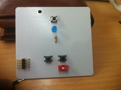
I am in the process of modding my G4 case (yet another clone of this) and I didn't feel like modding the existing front panel, so I created a new one. I skipped on the dual LED, since I don't like blinking lights so I have a single LED (used as PWR LED), Power SW, Reset Sw and the NMI switch I will be using as a CMOS clear (which is optional if the dip switch is ON).

I want to apologize for the blurry photo taken with my iPhone.
IMG_0036.jpg
What do you think?
 
Very nice work! How did you do it? I did something similar for mine with a bit of vero board since I wanted to keep the old front panel, it's on my thread here http://www.tonymacx86.com/powermac-g4/134267-power-mac-g4.html

Right back near the start as it was the first thing I did, I think it's nicer than hacking up the old board, plus you can pick whatever colour led you want, I chose blue.:lol:
 
I used EAGLE (pcb design program) and a caliper... When the design was done I gave it to a PCB foundry and they made it. In order to become cheaper they made me 12 PCBs (11 of which I will sell on ebay).
 
Still available ?
 
Today I received the low profile tact switches and soldered them to the first PCB. I just need to test it and if all goes well I will create the ebay listing tomorrow. Stay tuned!
 
See the tonymacx86 Rules and Policies:

Advertising and Solicitation

  • No member can ask, accept, offer or provide any form of compensation to any other member for any form of assistance.
  • We do not allow members to post threads or to send private messages or emails to other members that advertise products or services or solicit for funds or donations.
  • Members cannot post advertisements or notices for eBay auctions, Kickstarter projects, Craigslist listings, personal sales or contests.
  • Posting any affiliate or referral links, or post anything asking for a referral is not allowed and will be removed.
 
The red DIP switch is for "permanently" disabling the 3rd button (the concaved one on the plastic case), which I intent to use as a CLR CMOS. You don't want anyone else accidentally clearing the CMOS while the PC is running.

I did not intend to make the original ribbon cable work for 2 reasons.
  • Length of the cable. It may not be long enough in order to reach the pin header of the (m)ATX mobo.
  • If the 3rd button is used as a CLR CMOS, the CLR CMOS pin header is somewhere else on the board there is no way to split the apple ribbon cable.

Here is a photo of what cable I used to connect to the mobo pin headers.
IMG_0042.jpg
 
Status
Not open for further replies.
Back
Top