Contribute
Register

iMac G5 17" A1144 Display Connector

Status
Not open for further replies.
Joined
Sep 7, 2015
Messages
7
CPU
ARM
Mac
  1. iMac
Classic Mac
  1. 0
Mobile Phone
  1. 0
At first i have to thank tonymacx86 forum, i bought an A1144 and with the tutorials and Mods here i want to mod my A1144 and put at first a RasPi inside ( use it for Kodi only).

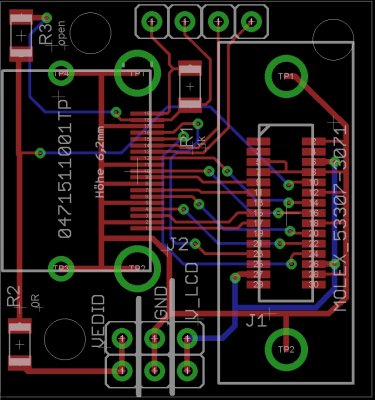
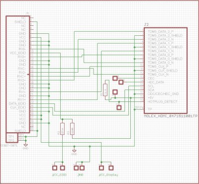
I have not found a board to connect a hdmi and the G5 monitor connector, so i tried to build one myself. So here it is the first try, as eagle 6 file.

In the zip below i attached the lib for the G5 connector, i think it is a molex 533073071 (you can find it on digikey) and the first try of the board ( board and sheet, with an hdmi connector wired like here : http://www.tonymacx86.com/imac-mods/124456-ersterhernds-imac-g5-isight-17-project.html#post759772 , or on dremeljunkies page).

EDIT : November 5 2015 : Dont use this Circuit, see post #6
 

Attachments

  • G5_con_lib_sch_brd.zip
    14.7 KB · Views: 280
Last edited:
if you dont have eagle, here two pics of board and sheet
board.jpg
sheet.jpg
 
I have ordered them to OSH Park, let's see if this works. I think this will make easy to mod iMacs :clap:
 
Sorry, i did a mistake in my first try, so DON`T use it . Pin 26 is VCC 3v3 @ isight 17" and 12V @ imac 20" so it is not EDID-CLK, EDID-CLK is pin 24 !! You can damage the EEPROM of the Display.

The other thing you have to do is, you have to unsolder the VCC and GND Wires, which come from the LCD and solder them to extra wires to connect them to you supply. So this circuit is not "plug and play" without soldering :(

I did another version without the mistake and plug and play, but have not posted it here because i thought there is no interest.

Edit , here the new version i made:
( i will order this time the board myself, from china, so wait till i have it, i will test my board and post the result here )
Now you see the difference.
You connect de HDMI cable, the LCD cable and max tree wires from your supply.
If you use a isight 17" (like A1144) you have to put 3.3V on VCC_EDID and V_LCD and GND in the middle. If you use 20" (like A1076) you need 12 V on V_LCD and 5V on VCC_EDID and GND in the middle. Thats all.

Note:
R1 is the 1k Hotplug Detect Resistor. You can use a SMD 1206 resistor with 1k value or you can use a THT one, using the first and second hole (from the 4 holes on the top edge)

The modifications from this forum always power the EEPROM / EDID from its own supply so thats why R2 is 0 Ohm and R3 is open, so you can choose what voltage you put on VEDID.

Normaly the EEPROM (were the EDID is) of the display is supplied from the device ( PC or XBOX etc.. ), if you want that you have to swap R2 to R3; -> R3 = 0 Ohm = Bridge and R2 is open
 

Attachments

  • board_v2.jpg
    board_v2.jpg
    207.8 KB · Views: 509
  • G5_con_lib_sch_brd_v2.zip
    15.7 KB · Views: 285
  • sheet_v2.jpg
    sheet_v2.jpg
    338.7 KB · Views: 451
Last edited:
Sorry, i did a mistake in my first try, so DON`T use it . Pin 26 is VCC 3v3 @ isight 17" and 12V @ imac 20" so it is not EDID-CLK, EDID-CLK is pin 24 !! You can damage the EEPROM of the Display.

The other thing you have to do is, you have to unsolder the VCC and GND Wires, which come from the LCD and solder them to extra wires to connect them to you supply. So this circuit is not "plug and play" without soldering :(

I did another version without the mistake and plug and play, but have not posted it here because i thought there is no interest.

Edit , here the new version i made:
( i will order this time the board myself, from china, so wait till i have it, i will test my board and post the result here )
Now you see the difference.
You connect de HDMI cable, the LCD cable and max tree wires from your supply.
If you use a isight 17" (like A1144) you have to put 3.3V on VCC_EDID and V_LCD and GND in the middle. If you use 20" (like A1076) you need 12 V on V_LCD and 5V on VCC_EDID and GND in the middle. Thats all.

Note:
R1 is the 1k Hotplug Detect Resistor. You can use a SMD 1206 resistor with 1k value or you can use a THT one, using the first and second hole (from the 4 holes on the top edge)

The modifications from this forum always power the EEPROM / EDID from its own supply so thats why R2 is 0 Ohm and R3 is open, so you can choose what voltage you put on VEDID.

Normaly the EEPROM (were the EDID is) of the display is supplied from the device ( PC or XBOX etc.. ), if you want that you have to swap R2 to R3; -> R3 = 0 Ohm = Bridge and R2 is open

Awesome :clap: I can only understand about the half of what you wrote but still awesome :crazy::p:lol: Also, so good to see the modification, and I have something to say: Always share your modifications and your progress with the community, even if you tough that nobody gives anything about it. Maybe nobody takes it at the moment, but you'll see that with the time somebody will get interested in what you were doing (in this case MacTester and me :p). That's the way to be a bigger community :);)

Can't wait for the results about your PCB:beachball:
 
Any news? I'm going to start my mod, and this will be just perfect
 
Status
Not open for further replies.
Back
Top