- Joined
- Nov 25, 2013
- Messages
- 12
- Mac
- Classic Mac
- Mobile Phone
Hello Everyone,
After a long long time following the mods here at tonymacx86, in december I had the chance to get an iMac G4 17” for a bargain price – about 30 USD. The seller said, that not so long ago it worked fine but they moved and it no longer boots. So bought as a “not working” machine. The cosmetic condition looked okay, with some mark of water damage (limescale?) at the bottom plate. Anyway I bought it… I can use parts of it later if the screen is not working... so here goes... Yet Another NUC iMac G4!
Most of this mod is in the “planning” stage, some parts I already have. Will take a few months I think I would like to thank everyone here at tonymacx86 with the great mods and ideas as it moved me to get an iMac, try to mod and share my part
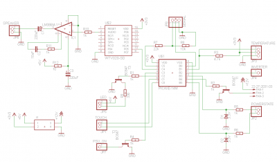
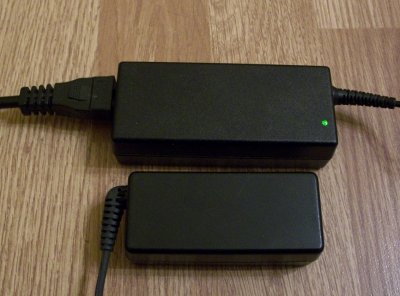
The hardware side is a NUC 3217 mobo (first revision without the USB header but I will solder one following this guide: http://www.whitebream.nl/nuc_usb) with 8Gb RAM, SK Hynix 256Gb SSD, PicoPSU (wide input) to run everything else. On the power supply side I plan to use a Toshiba Toughbook PSU (16V 60W), we have these at work and they look a lot smaller than the original one. I would like to have a DVD-RW and I also liked the idea of picaxe to control various things so:
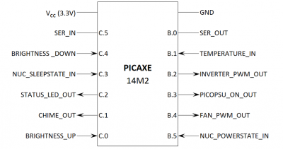
For the WTV020-SD I already converted an mp3 to ad4. See attachment…
The software is not final – not even close – but as soon as I have something worth checking I’ll post it. I'm pretty bad with electronics so...
About the iMac:
As I mentioned earlier it got wet and for a long time. Probably it stood in water for days or weeks. There are marks of limescale everywhere below the DVD. Also some rusting started at the bottom edge of the DVD drive. The fan and HDD looks fine though. Gave some quiet humming noise when turned on.
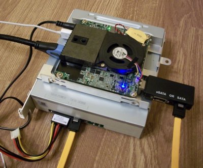
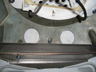
So I scrapped the internals except the DVD frame, put a Samsung SH-224 DVD drive into it in hope I can run it from USB – which I cannot confirm for now as still waiting for the USB-SATA adapter (sold as OSX compatible). This DVD drive’s front is replaceable/removable. Drilled 4 holes on the top side of the frame (95x90mm) and put the NUC on top of it with 4x 15mm M3 standoffs. I had to cut some part of the frame out to be able to access the HDMI ports.
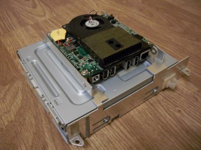
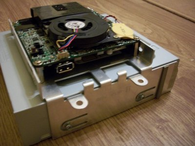
Waiting for internals, but holes drilled for touch sensors:
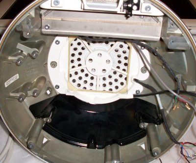
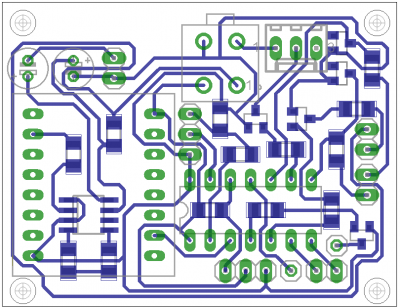
At the same time I started to sketch a new PCB. I do not want to re-use the original motherboard parts but design my own. A friend of mine can make PCBs with laser etching. Already ordered the sockets, will de-solder the 6-pin special audio connector and re-use on my PCB.
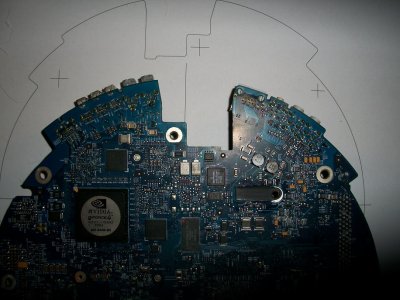
There are some items I'm still undecided: on one side of the PCB there is a miniVGA, 3x USB, 2x firewire and 1x RJ11 connector. I will use the 3x USB but the others I have no idea how to use. The oder side is clean and easy: 1x RJ45, 3x audio jack and a power button. How could i use those sockets?
So I'm about here with the iMac since mid december.
Sorry about the picture quality but I’m very bad with cameras… and electronics...
And also sorry about jumping around with topics but soooo much happened since I bought the iMac.
feczo
View attachment chime.zip
After a long long time following the mods here at tonymacx86, in december I had the chance to get an iMac G4 17” for a bargain price – about 30 USD. The seller said, that not so long ago it worked fine but they moved and it no longer boots. So bought as a “not working” machine. The cosmetic condition looked okay, with some mark of water damage (limescale?) at the bottom plate. Anyway I bought it… I can use parts of it later if the screen is not working... so here goes... Yet Another NUC iMac G4!
Most of this mod is in the “planning” stage, some parts I already have. Will take a few months I think
The hardware side is a NUC 3217 mobo (first revision without the USB header but I will solder one following this guide: http://www.whitebream.nl/nuc_usb) with 8Gb RAM, SK Hynix 256Gb SSD, PicoPSU (wide input) to run everything else. On the power supply side I plan to use a Toshiba Toughbook PSU (16V 60W), we have these at work and they look a lot smaller than the original one. I would like to have a DVD-RW and I also liked the idea of picaxe to control various things so:
- WTV020-SD “mp3” player for start-up chime with the original internal speaker
- DS18B20 temperature sensor + pwm fan control
- Sleep led
- Touch controlled brightness setting of screen

For the WTV020-SD I already converted an mp3 to ad4. See attachment…
The software is not final – not even close – but as soon as I have something worth checking I’ll post it. I'm pretty bad with electronics so...
About the iMac:
As I mentioned earlier it got wet and for a long time. Probably it stood in water for days or weeks. There are marks of limescale everywhere below the DVD. Also some rusting started at the bottom edge of the DVD drive. The fan and HDD looks fine though. Gave some quiet humming noise when turned on.
So I scrapped the internals except the DVD frame, put a Samsung SH-224 DVD drive into it in hope I can run it from USB – which I cannot confirm for now as still waiting for the USB-SATA adapter (sold as OSX compatible). This DVD drive’s front is replaceable/removable. Drilled 4 holes on the top side of the frame (95x90mm) and put the NUC on top of it with 4x 15mm M3 standoffs. I had to cut some part of the frame out to be able to access the HDMI ports.


Waiting for internals, but holes drilled for touch sensors:


At the same time I started to sketch a new PCB. I do not want to re-use the original motherboard parts but design my own. A friend of mine can make PCBs with laser etching. Already ordered the sockets, will de-solder the 6-pin special audio connector and re-use on my PCB.

There are some items I'm still undecided: on one side of the PCB there is a miniVGA, 3x USB, 2x firewire and 1x RJ11 connector. I will use the 3x USB but the others I have no idea how to use. The oder side is clean and easy: 1x RJ45, 3x audio jack and a power button. How could i use those sockets?
So I'm about here with the iMac since mid december.
Sorry about the picture quality but I’m very bad with cameras… and electronics...
And also sorry about jumping around with topics but soooo much happened since I bought the iMac.
feczo
View attachment chime.zip

