- Joined
- Aug 16, 2014
- Messages
- 27
- Motherboard
- Imac
- CPU
- G4
- Mac
- Classic Mac
- Mobile Phone
Antonis' Transmac G4 17''.
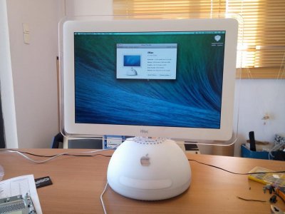
UPDATE no.4: The iMac is 95% ready. Build pictures will follow!
UPDATE no.3: I report the screen is working as it should and it is perfect!!! The cables on this Euro model were a little bit different than the one shown at various illustrations.
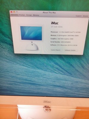
I m calling my build the Transmac, in other words, the 1Ghz Imac that wanted to be an 800 instead. I wired the screen with the 800mhz instructions and.... voila. Pictures further down this page.
UPDATE: Video on the opening post with the problem that seems to come from the 3.3v connection of the grey wires.
Dear friends,
Inspired from Nucimac G4, Dremeljunkie's info and MacTester's build, I decided to move on with my own G4 17''. Since I am in Europe I really wanted to have a 220V model. Fact is that a decent working one, cost me around $360 (around 285 Euros). I proceeded with my build as per the instructions of Ersterhernd's Nuci and Dremeljunkie. I have connected everything up and I have the following problem.
1) I should tell you that the computer was working fine as a normal G4. Lights, screen, audio everything.
2) When I tried to test the inverter on its own with the pico psu, I had the flashing backlight issue where I read that it could be a problem from the crocodile plugs for the ground connections.
3) I hard wired everything so as to be sure that the connections were ok.
4) I turned on my pico psu grounding pin 14-15. I tested all connections that they were giving the correct voltages.
5) I unplugged it and I connected all cables to it with snuggly fitting pin connectors.
6) When I turned it back on the pico's red led flashed quickly while making a very fast relay switching noise. After 3 seconds the led turned off. I reapeated this process 2 or 3 times and it still did the same thing.
Does anyone know what this means?
Thank you guys in advance.
Antonis
https://www.youtube.com/watch?v=FY8QmBabnzE&feature=youtu.be
UPDATE no.4: The iMac is 95% ready. Build pictures will follow!
UPDATE no.3: I report the screen is working as it should and it is perfect!!! The cables on this Euro model were a little bit different than the one shown at various illustrations.
I m calling my build the Transmac, in other words, the 1Ghz Imac that wanted to be an 800 instead. I wired the screen with the 800mhz instructions and.... voila. Pictures further down this page.
UPDATE: Video on the opening post with the problem that seems to come from the 3.3v connection of the grey wires.
Dear friends,
Inspired from Nucimac G4, Dremeljunkie's info and MacTester's build, I decided to move on with my own G4 17''. Since I am in Europe I really wanted to have a 220V model. Fact is that a decent working one, cost me around $360 (around 285 Euros). I proceeded with my build as per the instructions of Ersterhernd's Nuci and Dremeljunkie. I have connected everything up and I have the following problem.
1) I should tell you that the computer was working fine as a normal G4. Lights, screen, audio everything.
2) When I tried to test the inverter on its own with the pico psu, I had the flashing backlight issue where I read that it could be a problem from the crocodile plugs for the ground connections.
3) I hard wired everything so as to be sure that the connections were ok.
4) I turned on my pico psu grounding pin 14-15. I tested all connections that they were giving the correct voltages.
5) I unplugged it and I connected all cables to it with snuggly fitting pin connectors.
6) When I turned it back on the pico's red led flashed quickly while making a very fast relay switching noise. After 3 seconds the led turned off. I reapeated this process 2 or 3 times and it still did the same thing.
Does anyone know what this means?
Thank you guys in advance.
Antonis
https://www.youtube.com/watch?v=FY8QmBabnzE&feature=youtu.be