Contribute
Register

iMac G3 (slot) mod - Video Connector

Status
Not open for further replies.
Joined
Feb 19, 2014
Messages
6
Mac
  1. 0
Classic Mac
  1. 0
Mobile Phone
  1. 0
iMac G3 (slot) mod : problem with Video Connector Wiring

Hi,

I have been trying (to no avail) for the last few days to include a mini ITX-PC board in an iMac G3 slot-loading while keeping its PSU and CRT.

I made a short custom cable to internally connect the VGA output of the PC board to the iMac HE10 20-pin video connector but it looks like I am still missing some pins.
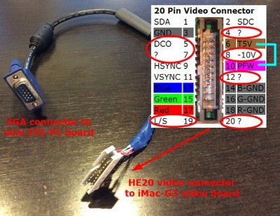
forums.jpg

Even when the +5V-trickle (T5V) and PFW signals are shorted, I cannot hear the "PONK" sound of the CRT charging up ... (needless to say that the CRT works quite right with the original iMac logic board).

Has anyone made such a mod and did you find out if pins 4, 5, 7, 8, 12, 19 and 20 have to be connected and where to ?

Thanks for any help you could give me on this issue.
 
Hi everyone,


Unfortunately, I could not find any relevant info on the internet despite the numerous hours of google search that I made ... :(


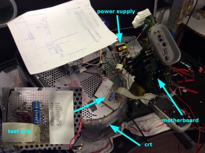
So I have decided to make a test board to parse every single signal that comes out of the mother board and connects to the video card :

forums2.jpg


What I found is that, besides the "classical" red/blue/green, hsync/vsync and ground signals, most of the other signals are NOT used BUT the two SDA and SDC signals (respectively pins 1 and 2).


When connected to an oscilloscope DURING THE BOOT, these two signals show that the motherboard raises them to +5V then real quick ( after a few 100th of msec ) applies a particular pattern sequence (logical states +5V and 0V) then finally leaves them to +5V all through out.
From this point on, the "PONK" of the CRT is heard, and everything works out right !


Then, you can even drop the two signals (SDA and SDC) to 0V, no matter what : the iMac is definitely ON and so is the CRT.


My deal now is to find how to replicate those TWO short sequences (they are both different, I mean SDA seq is not the same as SDC seq !) WITHOUT the main board.
And then, I should be ready to get rid of the iMac motherboard and install a PC board in the iMac G3 !


Any hint, idea, suggestion, reflection whatsover is VERY welcome ...
ym58
 
great post dude!!
Finally someone on the same line as myself.
Im in the plan of doing the same but using an eMac G4 (I love those things, and they are EVERYWHERE in my country - Argentina-), meaning: Keep the lovely CRT, adapt atx Psu and Mini-Itx mobo.

I´m a laptop tech, electronic level, fulltime worker and also as hobbie. I´m able to do difficult test for this project.
I´m going to look for your efforts, and report to you of mines!!
Keep on going!!
 
"I have been trying (to no avail) for the last few days to include a mini ITX-PC board in an iMac G3 slot-loading while keeping its PSU and CRT"

Maybe the idea of keeping the PSU is not the best idea?
If you are planning on using a pc motherboard you should include a actuall, strong standard ATX PSU?
 
I have (Right now, in my hand) the "can type" module from a CRT of a dead imac g3 dv400, looking at Ic's and a bunch of test points and labels on it.
Do you want pictures of the thing?
I'm able to take it apart and kipp the circuit board clean for analyzing, and even i have a multimeter...

For example, im looking right now at this IC: LM2437 (http://www.ti.com.cn/cn/lit/ds/symlink/lm2437.pdf)
YOU HAVE TO check that pdf!!!
 
Hi Patricio,

I am happy someone else somewhere in the world has the same points of interest as mine !

Yes you are right, the PSU has got to be changed for a stronger one since the built-in iMac's PSU is very weak (maybe less than 100W), even to power a mini-ITX main board !

Maybe, you may also have a look to this other topic where I had, some time ago, been more elaborative and detailed to describe the problems that I had to face.

My main problem is to be able to locate ***where*** I can force the CRT ON when the iMac is powered ON.

To an electronic standpoint, that should NOT be a problem at all, but the point is that no-one could ever get a hold of the schematics of the CRT power board (known as the PAV board) !

Don't hesitate to come back to me here or by PM.

Yann
 
Looking at the "can type" board of the imac g3 dv400 right now (I disassembled and unsoldered the steel plate on it)...

The sda and scl signals you are ineterested to, point directly to pins 5-6 of 24lc028; Here is the shematic (Please read carrefully the protocol of up´s and down´s of the device datasheet, i think that should equal your tests):
http://www.alldatasheet.com/datasheet-pdf/pdf/64437/HOLTEK/24LC02.html

This is known as i2c protocol, and is being used for a long time on electronic devices (The good thing: complex comunication with only 2 wires).
I think the way to go is to record on paper the patern, and then to use a pic (Programable Integrated Circuit) like the 16f84a - I have a few here- to trick the dam thing.

I´m able to make the program and record to it, the problem right now is i dont have a working G3 (If you write the pattern, i may buy one).

Keep on going!!
Note: My English is sad, and i´m writing as fast as i´m able. Sorry.
 
Maybe (With luck) some old Apple´s designer (from "a world of better designer´s") of the 90´s (Retired already) read this and says: "Ok guys, you need to pull-up pin x on here...and it will work as a standard monitor..."
 
Hello Patricio,

Firstly, what do you mean by "can type" ?
This is the second time you use this term and I am kinda confused ...
---
I am an old school electronician.
I am a bit aware of cabled logic and programmed IC's but I am a bit stubborn also ... (I am French ;-)

Let's call your 24LC028 IC a "black box" and let's consider SDA/SDC are inputs to this black box and the fly-back transformer power circuit is connected to the output of this black box.

We don't really want the newly hacked G3 to be as clever as before, we just want it to power-on the CRT everytime we switch the machine ON ... no matter what !

So why should we try to replicate the SDA/SDC sequence with a somewhat 'complicated' PIC whereas we could simply FORCE the output of our black box to ON ?!!!

That should not be a real problem, should it ?

Then, once this is done, anytime the hacked G3 is switched ON, both ITX-PCB and CRT go ON ... and everyone is happy with that, particularly the user who can watch the BIOS POST running on his old-timer screen ;-) !!!

What do you think ?
ym58
 
Maybe (With luck) some old Apple´s designer (from "a world of better designer´s") of the 90´s (Retired already) read this and says: "Ok guys, you need to pull-up pin x on here...and it will work as a standard monitor..."
exactly !
our last posts just crossed each other !
 
Status
Not open for further replies.
Back
Top